Students: Arjan Neelis, Emre Gözcü, Margot Driessen, Niels Goos
Introduction
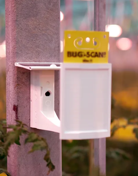
Pats is a start-up company in Delft that monitors and eliminates pests in greenhouses. One of their products is the Trap-Eye. The Trap-Eye consists of a housing with a solar panel, camera and a sticky card to catch pesticides. The pesticides are monitored with the camera.
Original Situation
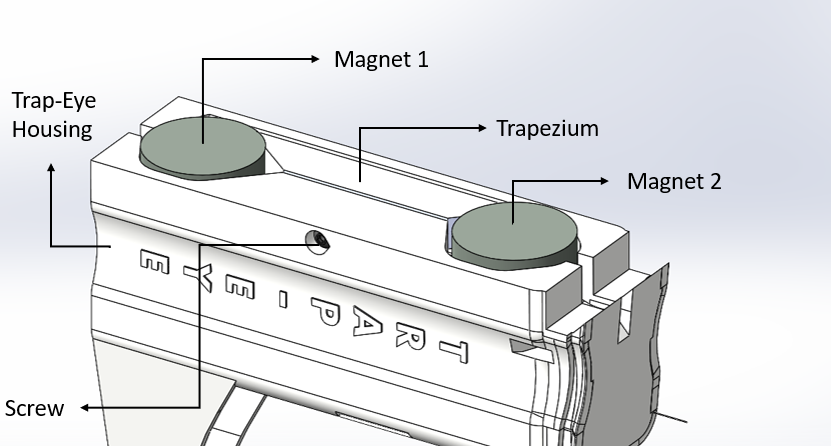
The Trap-Eye housing is 3D printed at the company and assembled by hand. This consists of the following steps:
- picking up and placing the magnets,
- picking up and placing the trapezium
- picking up a screwdriver and screwing in the screw so secure the magnets. and picking up a screwdriver and placing the screw to secure the magnets.
- Checking the placement of the magnets by placing it on a straight magnetic wall to check if it sticks correctly.
The problem
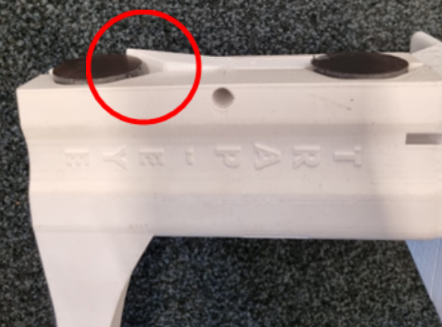
The placement of the magnets can be tricky and is not always done perfectly. This is very important because otherwise the Trap-Eye won’t stick to the poles in the greenhouses and falls down.
Another problem is the trapezium and its alignment. It can happen that when screwing it, the trapezium turns a bit and
it fails to tighten the magnets and sticks out above them.
A cobot can place the magnets and trapezium more consistently.
The end goal of the company is making the production of the Trap-Eye completely automated. From tacking it out of a 3D printer until the final assembly step.
The solution
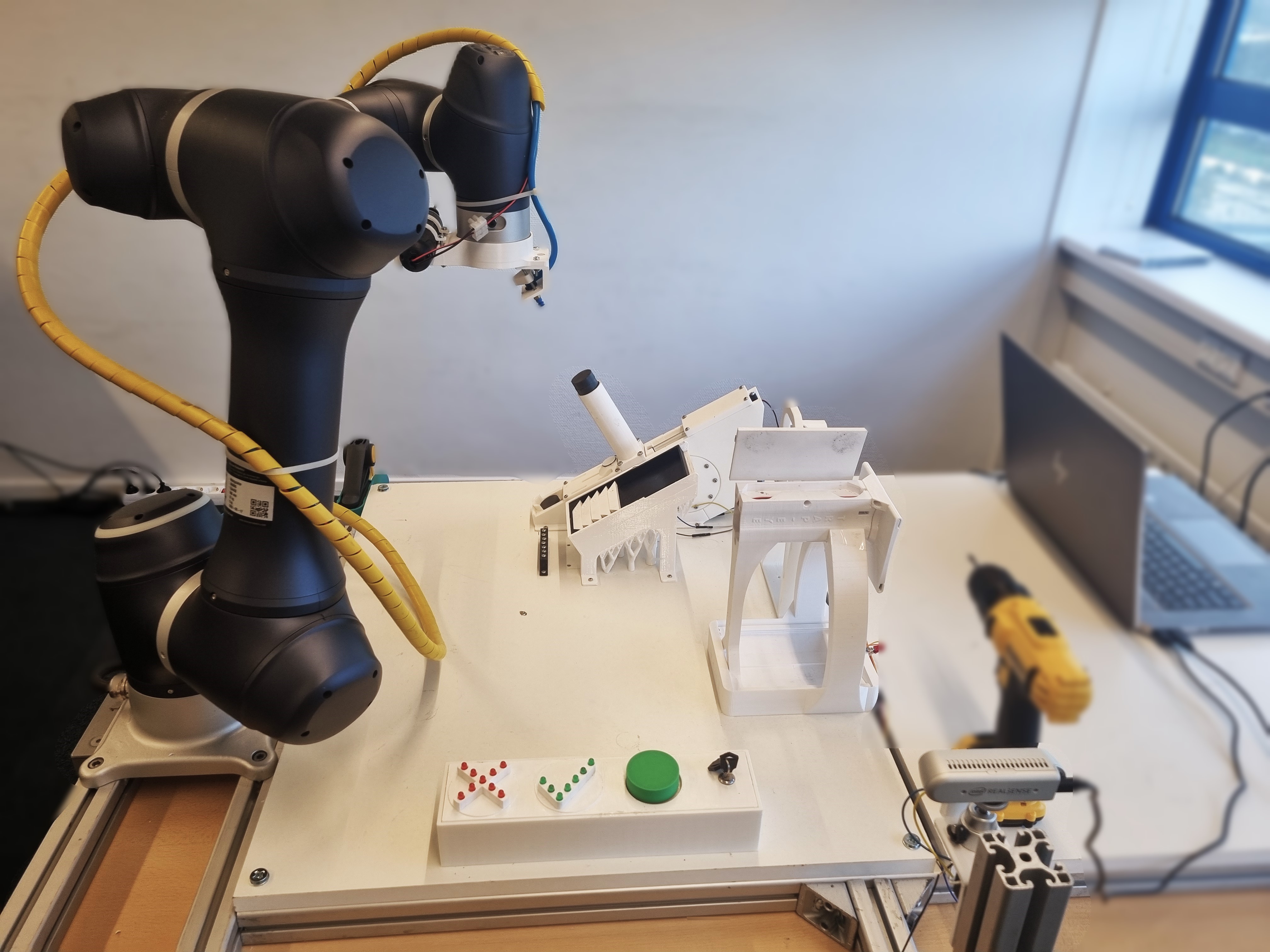
For about 5 weeks we worked together on this project and came up with the following solution.
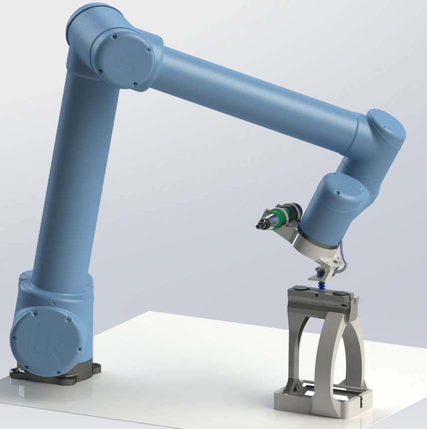
A Trap-Eye housing is placed in the carrier. The cobot uses a vacuum gripper to pick and place the magnet and trapezium. After the cobot will pick up a screw and screw it in the Trap-Eye to secure the magnets. The last step is the checking of the magnet alignment. If the alignment is correct the Trap-Eye can be taken out of the carrier and a new assembly can begin.
Trap-Eye Carrier
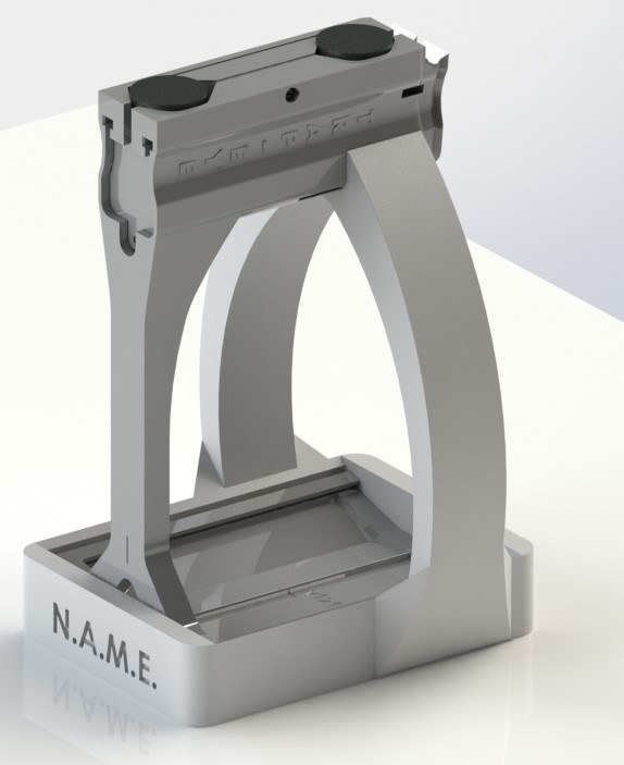
The Trap-Eye carrier makes sure the Trap-Eye housing is always at the same spot and is in a stable position. A limit switch checks if the Trap-Eye housing is placed correctly. If so, the automated assembly can start.
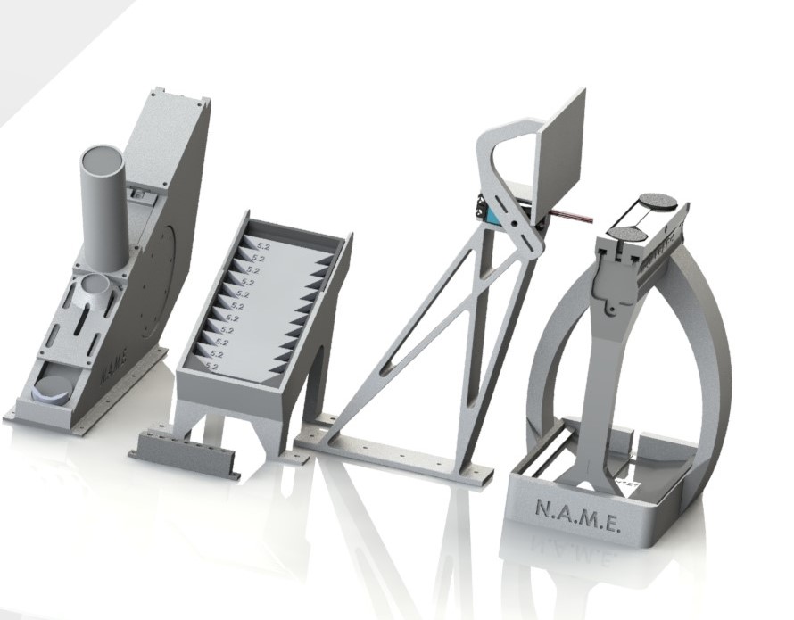
Magnet feeder
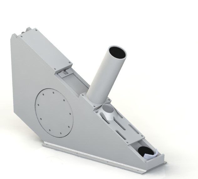
The cobot is programmed to pick up the magnets and place them one by one. The magnets can be inserted in the tube. A linear actuator pushes one magnet at a time down the slide. A small roof makes sure that the magnet on the slide does not get pulled to the side of the tube by the magnetic force of the magnets that are sticked on top of each other. Next to this a smaller magnets is placed on top of this roof that repels the magnet on the slides and gives it an extra push. The end of the slide is shape with two angular sides so the tolerances of where the magnet is picked up is reduced. A hall sensor checks if the magnets is pushed down correctly and communicates this to the cobot.
Trapezium feeder
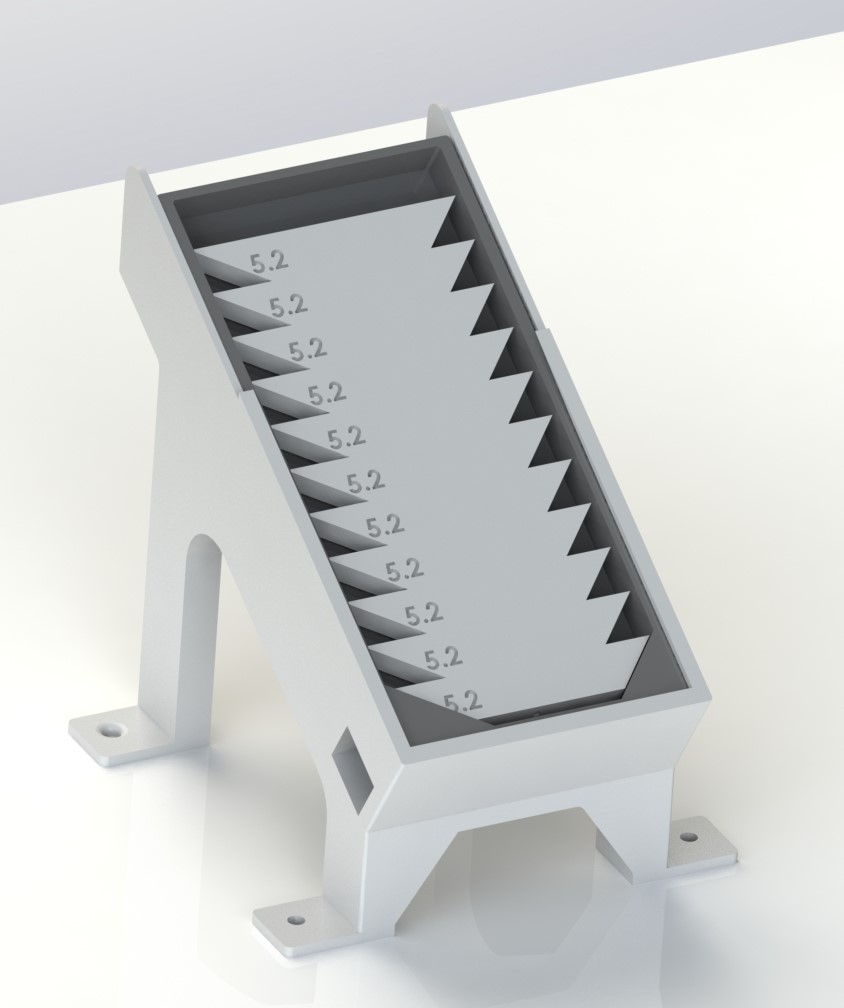
The trapezium feeder is also a slide in which multiple trapeziums can be stacked on top of each other. The tray in the slide can be “pre-filled” so switching to a full tray takes about 8 seconds. The trapezium feeder is a concept which later can be changed to directly be attached to a continuous 3D printer or the cobot can pick and place the trapeziums directly out of a 3D printer to reduce the steps which are necessary for the assembly. An Infrared sensor checks if the trapezium is at the end of the slide and communicates this to the cobot.
Screw feeder
The screw feeder is a 3D printed part that can hold up to 7 screws for testing. The cobot moves to the location above the first screw and turns on the screwdriver to find the centre of the the torx screw. The screwdriver bit is magnetic so it can pick up the screw.
The screw feeder is a proof of principle and will be replaced by a screw feeder.
Vision system and servo arm
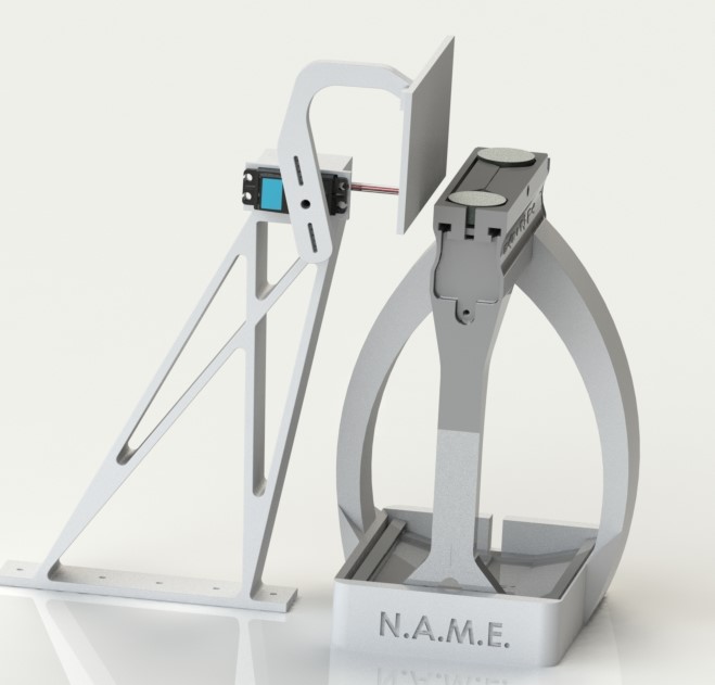
Before inserting the screw, an arm actuated by a servo, will push the magnets and the trapezium down slightly. This ensures that the magnets and trapezium are placed correctly.
After the screwing the arm moves back up and functions as a white background for the vision. Across from the Trap-Eye carrier a Real Sense camera is installed. The camera runs on a vision program and checks if the magnets are aligned correctly.
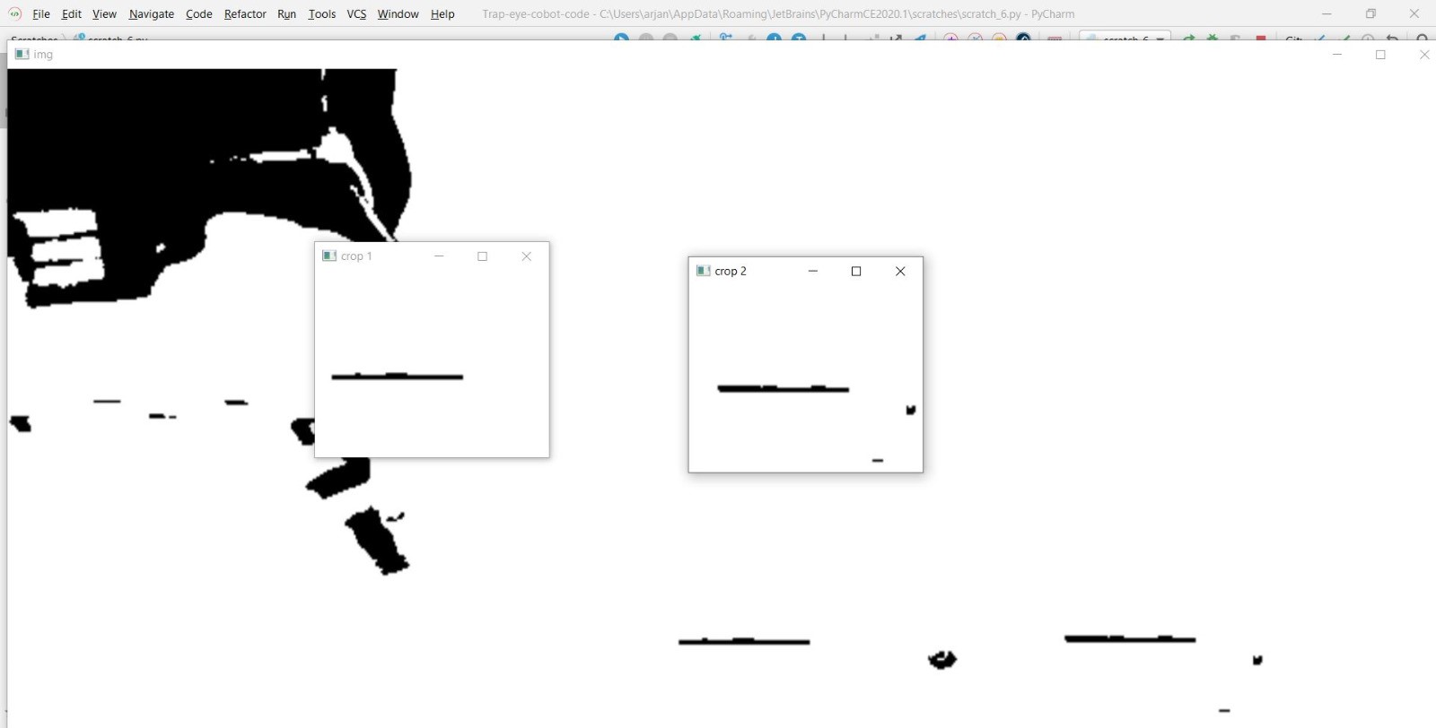
The whole assembly solution with the cobot is designed, so that the alignment of the magnets and trapezium should always be correct. Even so, if a failure occurs the vision system will detect this by measuring the angle or tilt of the magnets. If this happens the Trap-Eye housing has to be checked. A failure might have occurred during printing or something else is wrong.
With this solution, checking by hand if the Trap-Eye sticks to a straight steel wall, is not necessary anymore.
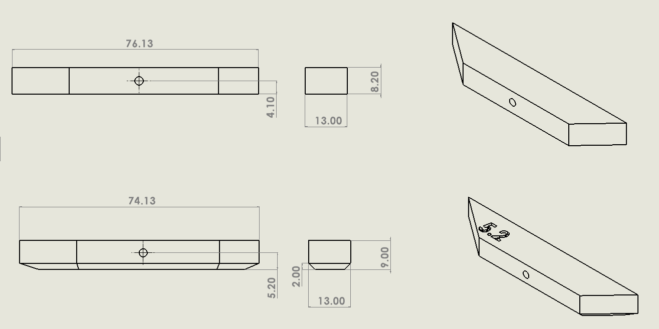
Changes to the trapezium design
To reduce failure of the trapezium becoming skewed when screwing, the design of the trapezium is adjusted a bit. By increasing the hight of the hole for the screw the trapezium is more tight in the housing and can’t wiggle anymore. We noticed that this was most of the time the problem when screwing in the screw.
Next to this the edges of the trapezium have a R2mm chamfer added. This way the trapezium slides in between the magnets more easily.