Students: Bastiaan Barteling | Peter-Bart van Burik | Chris van Zandvoort
Introduction
At Scabro Innovations B.V. in Katwijk Aan Zee, they are researching, developing and assembling a 2.8 meter wide VTOL (Vertical Take-Off and Landing) fixed wing drone. This drone will be used in a wide range of sectors (medical, agricultural and military).
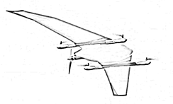
The drones are currently being produced completely by hand. The body of this drone consists of six different (shell) parts that are interconnected by braces. These parts have to be put together by means of adhesive. Because applying this adhesive is very difficult by hand, Scabro Innovations B.V. is looking for solutions to automate the adhesion process.
There are a few things that changed since last time. Since then not only the fuse without braces is finished, also the wings (with and without braces) are completed. The vision system is replaced and expanded. If there are any errors or Scabro wants to change something, it can be found in one of the manuals that were put together.
The challenges
- Creating an accurate and precise adhesive seam with the robot.
- Using the same amount of adhesive every time.
- Detecting the presence and the viscosity of the adhesive.
- Making an easy way for the operator to send information, and get information to and from the robot.
The solutions
General overview:
Module 1 | Feeding system: Brings the parts from the operator to the robot and vice-versa.
Module 2 | Bonding system:
Module 2.1 | Robot arm: Makes the movements across the surface of the parts.
Module 2.2 | End-Of-Arm-Tool: Holds the syringe from which adhesive is dispenced secure in the correct place.
Module 2.3 | Adhesive regulator: Makes sure the correct amount of adhesive is dispenced.
Module 3 | Vision system:
Module 3.1 | Adhesive check: Detects if adhesive is present and if the viscosity is right.
Module 3.2 | Syringe check: Detects how much adhesive is left in the syringe.
Module 3.3 | Overview camera: Takes a photo of the part before and after the process.
Module 4 | Safety system: Makes sure the operator can work with the robot safely.
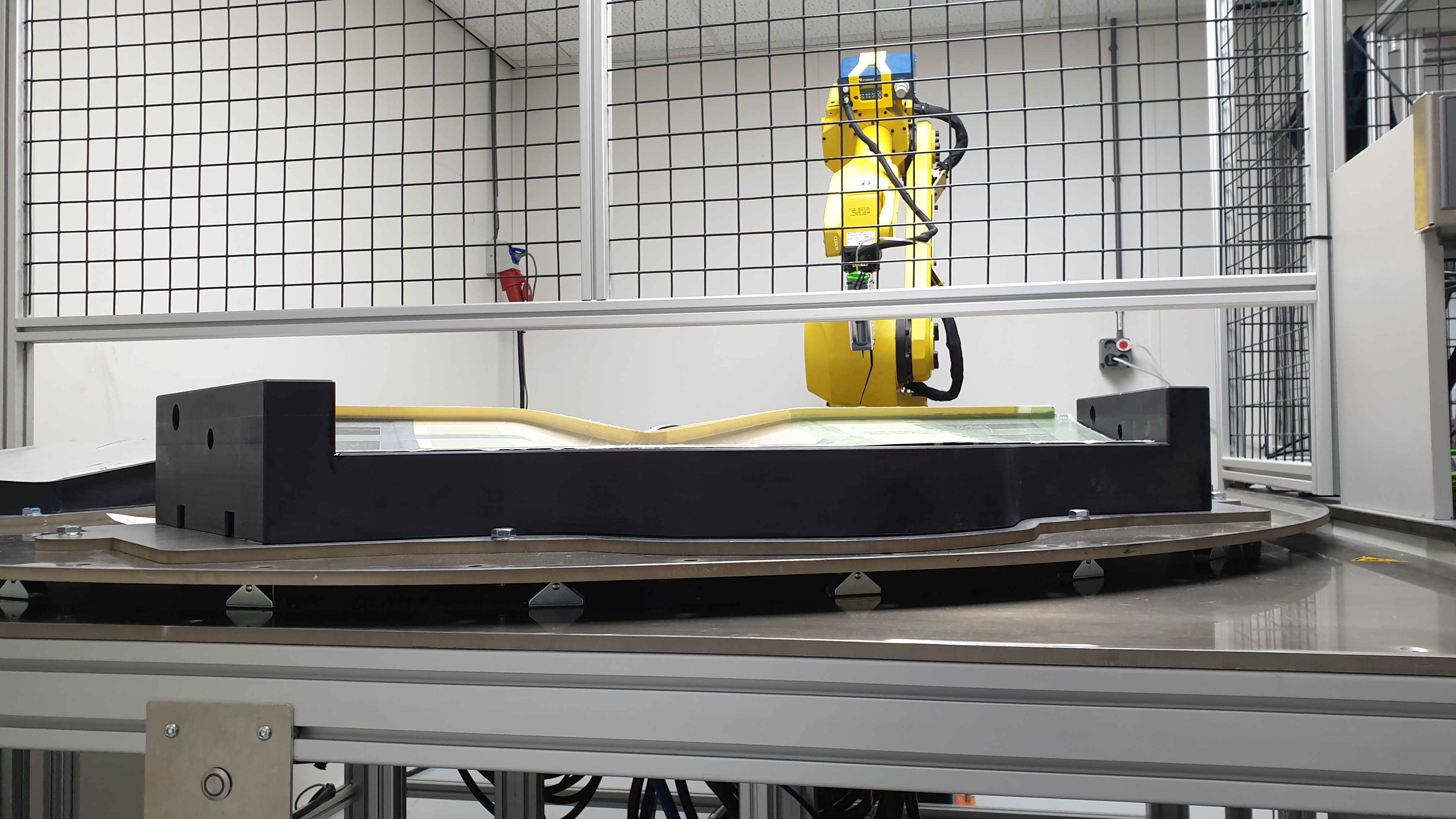
Module 1 (Feeding system)
The operator puts the part into the mold, turns on the vacuum and selects the right program. Then the servomotor (Fanuc single axis positioner) rotates the part underneath the robot. After the bonding process, it rotates back to the operator.
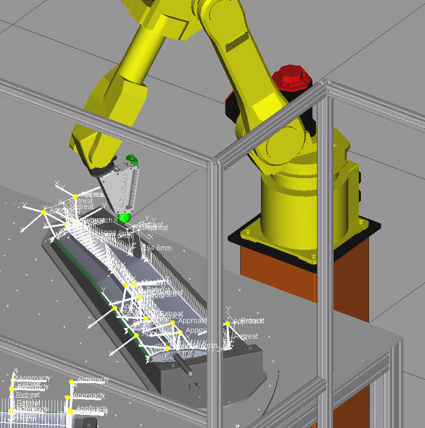
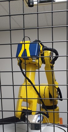
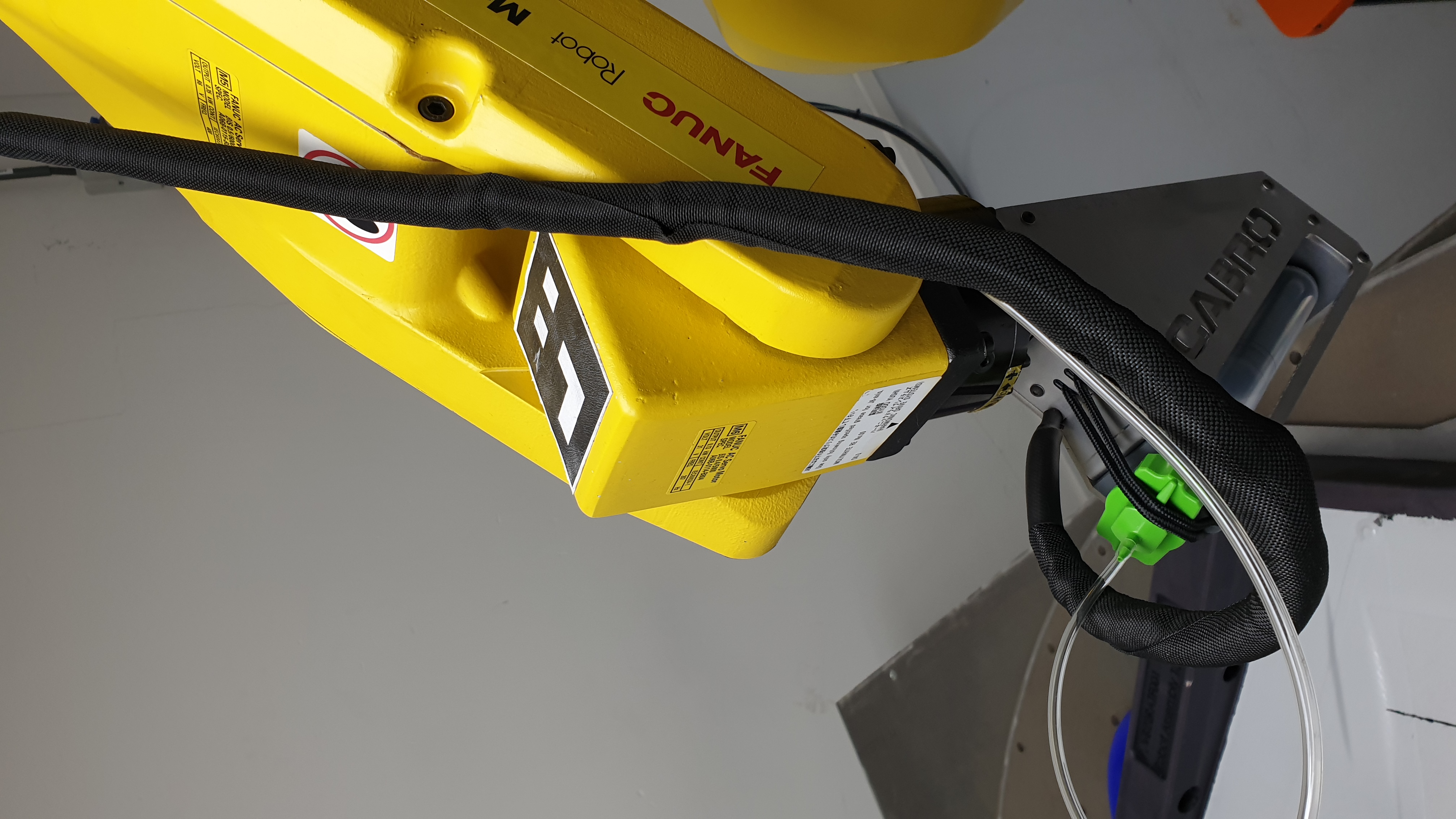
Module 2.1 (Bonding system –Robot arm)
The robot makes the movements across the surface of the part that needs to be adhered. The robot (Fanuc M-6iB) is provided to us by the client. The robot has been programmed using Fanuc’s own software named Roboguide.
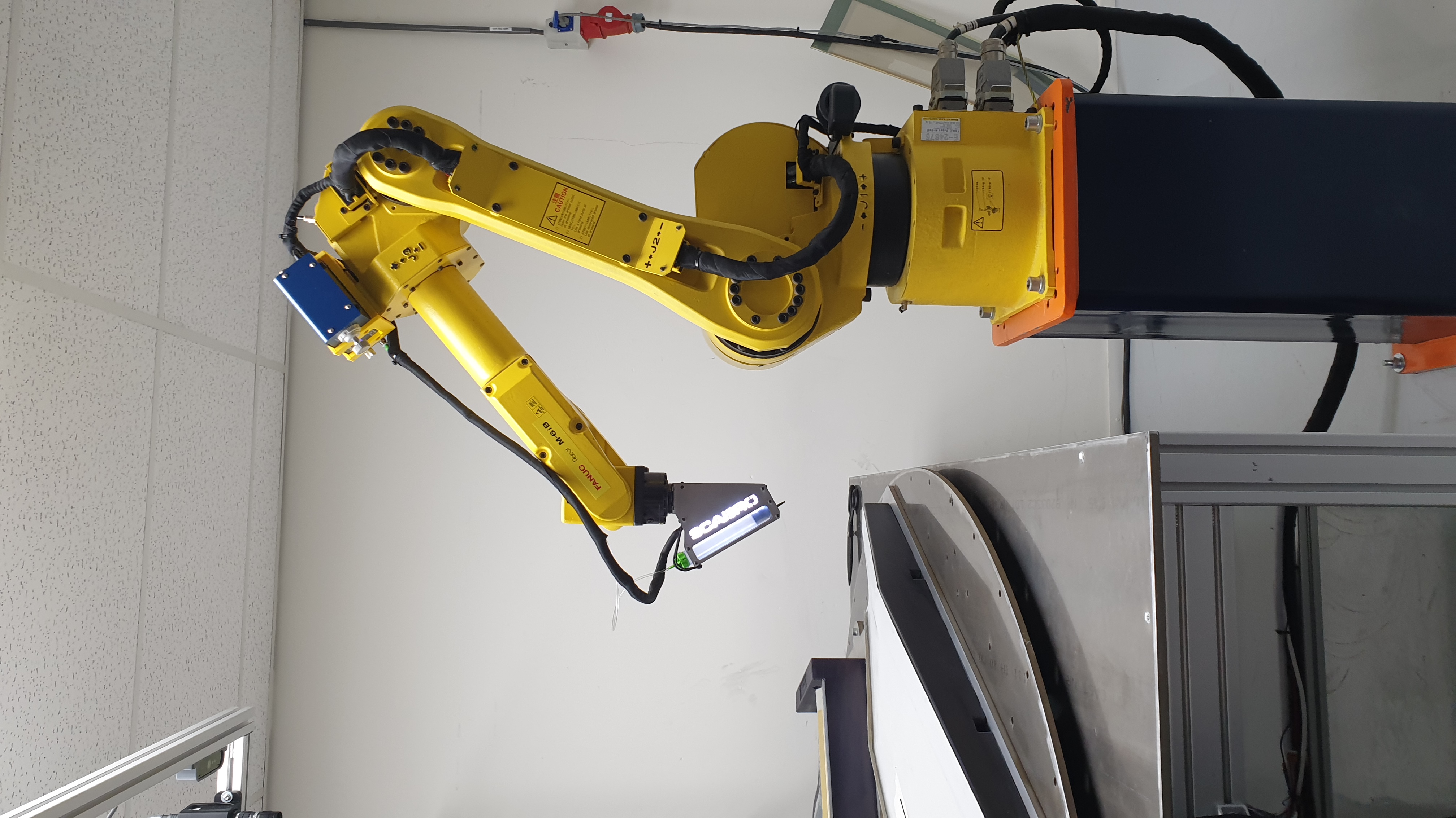
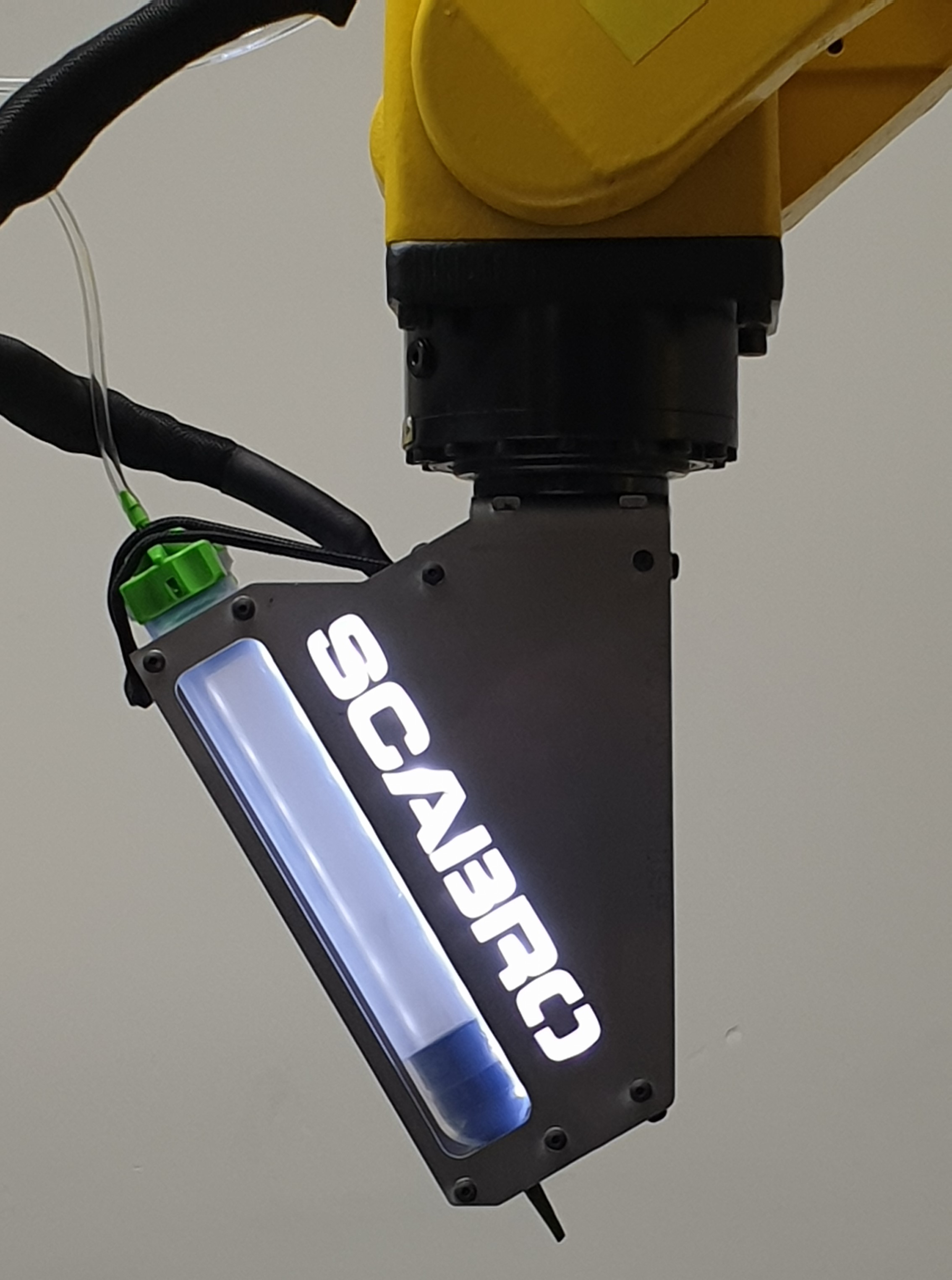
Module 2.2 (Bonding system – End-Of-Arm-Tool)
The End-Of-Arm-Tool holds the syringe, from which the adhesive will be dispensed. For the final setup, the 3D printed End-of-Arm-Tool was replaced with one made out of stainless steel. By using more robust materials this End-Of-Arm-Tool is now ready for production. The angle at which the syringe is placed has been changed from 45 degrees to 60 degrees for a more compact design.
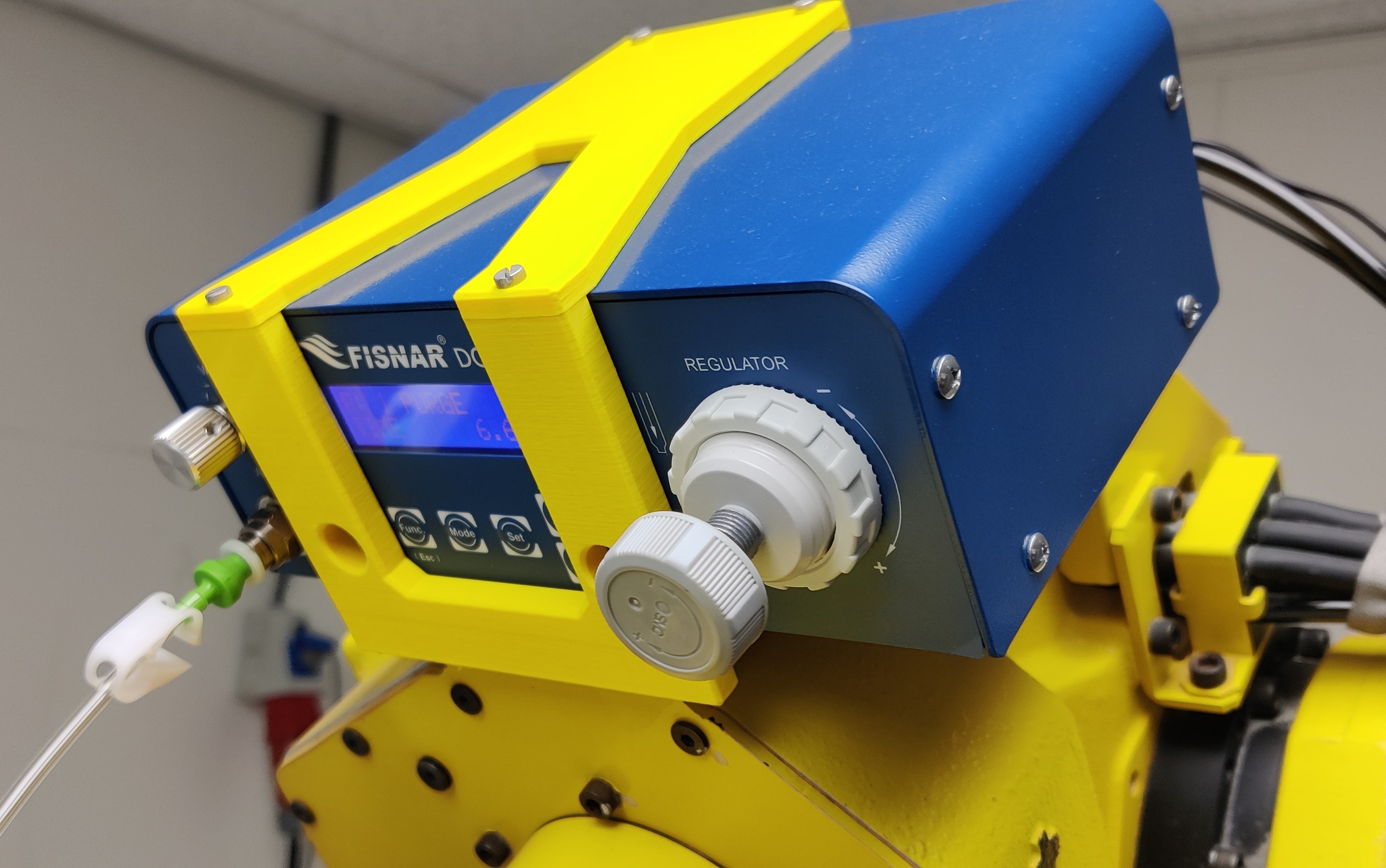
Module 2.3 (Bonding system – Adhesive regulator)
To make sure a consistent and correct amount of adhesive is dispensed, a regulator (Fisnar DC100) is used. This machine regulates the amount of air pressure used to push out adhesive.
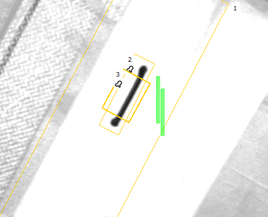
Module 3.1 (Adhesive check)
For the vision setup, the Visor V20 was chosen. This camera checks three things that are related to the adhesive. Firstly it checks if any adhesive has been placed. Secondly the vision camera checks if there are no air bubbles inside the adhesive using the so called blob function in Visor.
The thickness of the adhesive is related to the viscosity. The camera checks the surface area (pixel count) of the test strip. The Siemens PLC calculates the speed for the robot. Which results in the same thickness every time.

Module 3.2 (Syringe check)
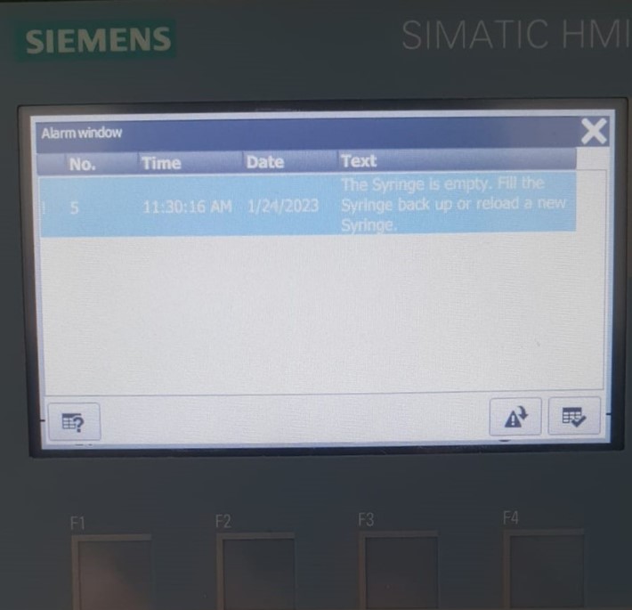
Just before every bonding process, the End-of-Arm-Tool moves underneath the camera and the V20 checks the amount of adhesive remaining in the syringe. If there is enough, the program continuous, but if there is not, the user will get a message on the HMI stating the current situation. In the last case, the operator can make the decision to either continue or stop the process.
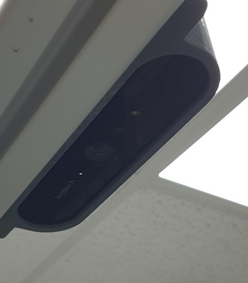
Module 3.3 (Overview camera)
To keep track of the quality and consistency of the production process, a camera takes a picture of the part before and after the adhesion. It does that by checking if the AruCo marker on top of the fifth axis is in a specific position.
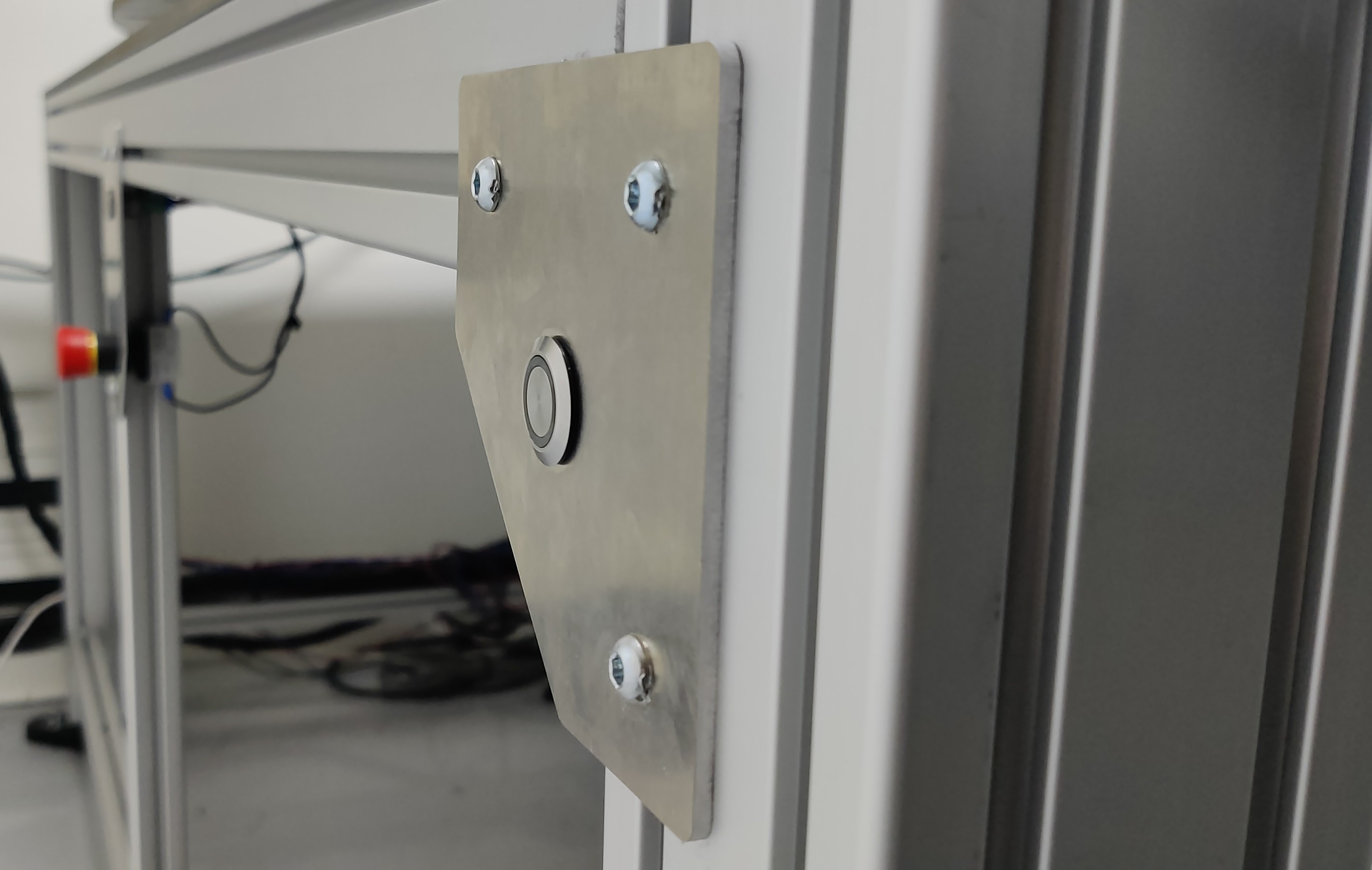
Module 4 (Safety system)
The safety system consists of a safety fence and safety switches around the system. To make sure the rotary table only rotates when no one is working on it, the operator has to push two buttons (one with each hand).
Main decisions
The Cognex was switched out with a new camera. The End-of-Arm-Tool was replaced by a more durable version.
We decided on not including the program for the fuse with braces. This is because, after some testing, we found out that not all the braces for the fuse are made with the same dimensions. These parts deviated so much, that an automated process was not an option. In the future these parts have to be altered for automation.
Conclusion
It was a huge opportunity to finish where we left of last semester and we’re very pleased with the setup we’ve delivered. Scabro is very impressed by the results we’ve booked and looking forward to using it.
Recommendation
The setup is ready to use. To make sure everything works as expected, Scabro needs to do a lot of testing by using the setup. Also the drone design needs to be adapted to an automated process.