Students: Bastiaan Barteling | Peter-Bart van Burik | Chris van Zandvoort
Introduction
At Scabro Innovations B.V. in Katwijk aan Zee, they are researching, developing and assembling a 2.8 meter wide VTOL (Vertical Take-Off and Landing) fixed wing drone. This drone will be used in a wide range of sectors (medical, agricultural and military).
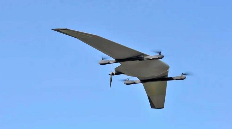
Figure 1: VTOL drone
The drones are currently being produced completely by hand. The body of this drone consists of six different (shell) parts that are interconnected by braces. These parts have to be put together by means of adhesive. Because applying this adhesive is very difficult by hand, Scabro Innovations B.V. is looking for solutions to automate the adhesion process. Due to the scale and complexity of this project, the focus in this part of the minor is on the bonding process of one scale part (the fuse).
The challenges
Applying this adhesive seam by hand is very difficult due to the precision and accuracy required. The consistency of the amount of adhesive is also really important. This is because the weight of the adhesive has a big influence on the stability of the drone. The task of adding adhesive seams should be done by the robot. Scabro Innovations B.V. also wants its employees to be able to prepare the shells while the robot is running.
Some of the biggest challenges are:
– Creating an accurate and precise adhesive seam with the robot.
– Building a system in which the operator and the robot can work simultaneously.
– Detecting the presence and the viscosity of the adhesive.
– Making an easy way for the operator to send information, and get information to and from the robot.
The solutions
General overview:
Module 1 | Feeding system: Brings the parts from the operator to the robot and vice-versa.
Module 2 | Bonding system:
Module 2.1 | Robot arm: Makes the movements across the surface of the parts.
Module 2.2 | End-Of-Arm-Tool: Holds the syringe from which adhesive is dispenced secure in the correct place.
Module 2.3 | Adhesive regulator: Makes sure the correct amount of adhesive is dispenced.
Module 3 | Inspection system: Detects if adhesive is present and if the viscosity is right.
Module 4 | Communication system: Makes the communication between the robot and the operator possible.
Module 5 | Safety system: Makes sure the operator can work with the robot safely.
Module 1 (Feeding system)
The feeding system consists of a rotary table on which the three different parts can be placed. These parts are put in their respective (vacuum sucking) molds. This will make sure the parts are always in the exact same location. The rotary table then rotates the chosen part underneath the robot. While the robot is bonding, the operator can place a new part. This rotary table is driven by a servomotor (single axis positioner).
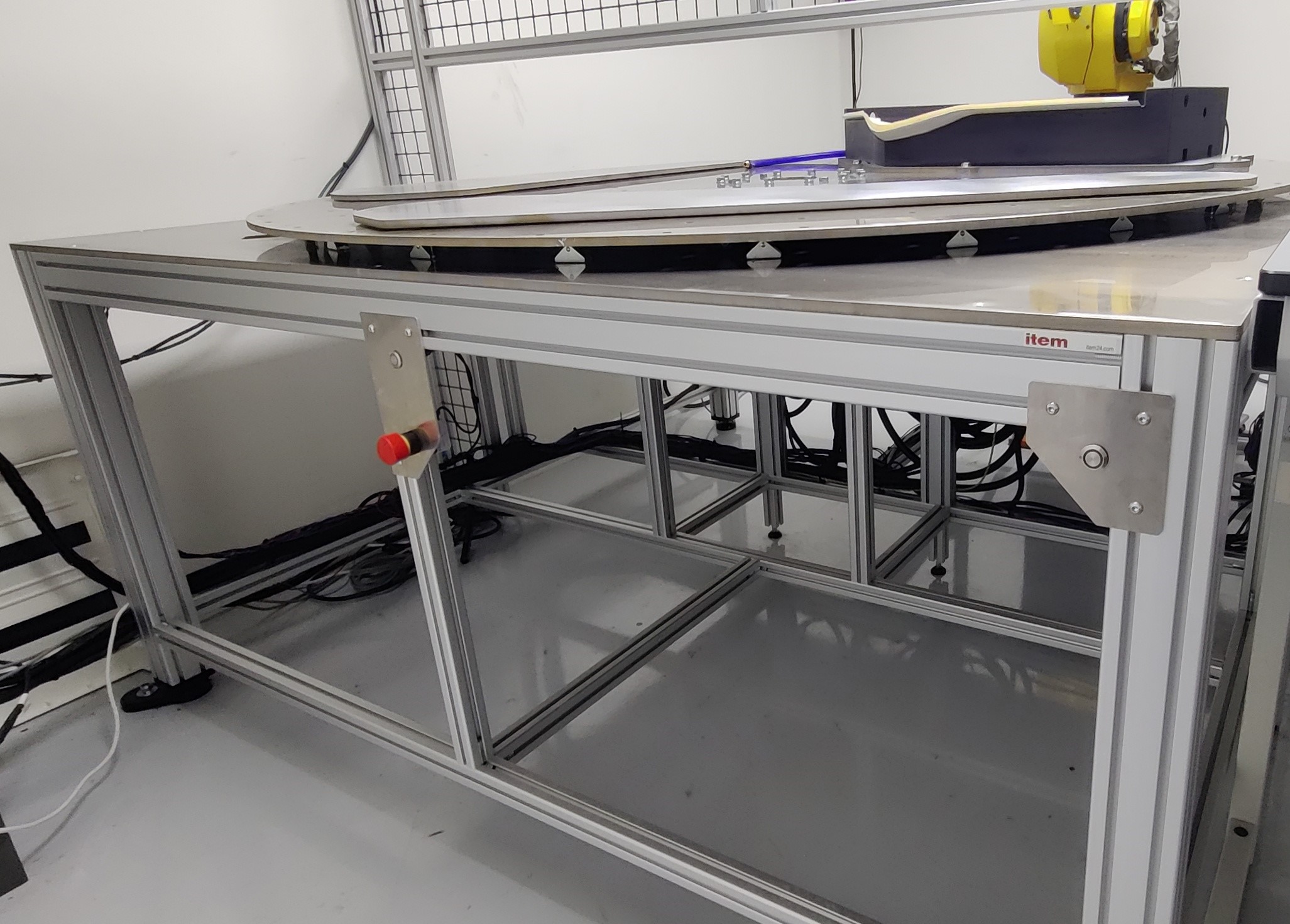
Figure 2: Rotary table
Module 2.1 (Bonding system – Robot arm)
The robot makes the movements across the surface of the part that needs to be bonded. The robot (Fanuc M-6iB) is provided to us by the client. Because this robot is an older model (2006), setting up the communication between the robot and the PLC was quite hard. The robot has been programmed using Roboguide. Roboguide is a program of Fanuc itself.
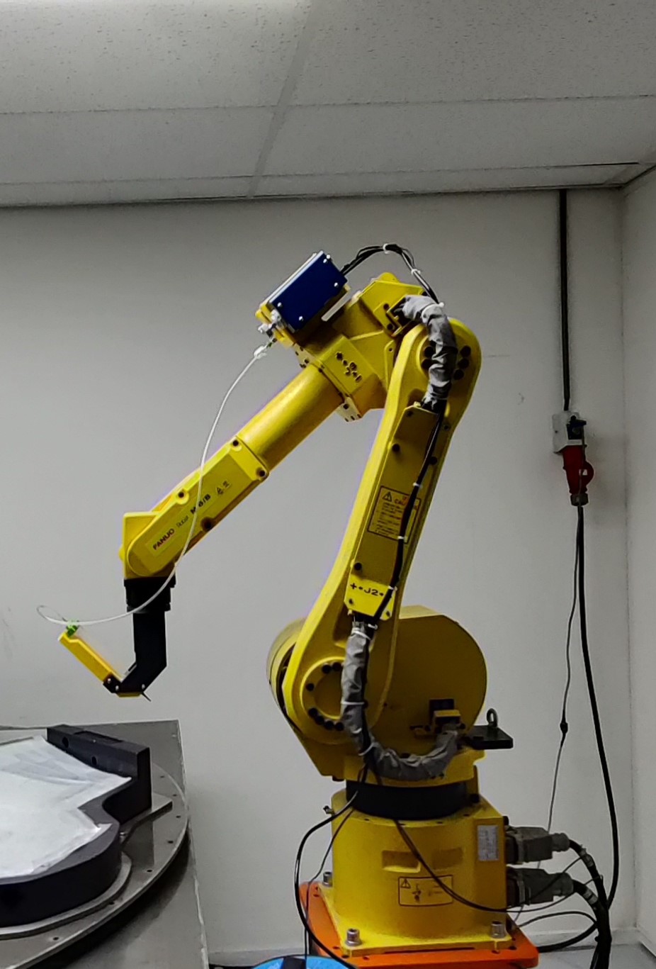
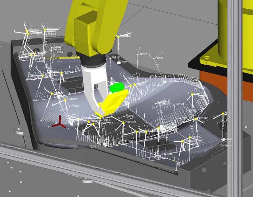
Figure 3: Robot arm (Fanuc M-6iB) Figure 4: Roboguide
Module 2.2 (Bonding system – End-Of-Arm-Tool)
The End-Of-Arm-Tool holds the syringe from which the adhesive will be dispensed. The End-Of-Arm-Tool is build in such a way that the adhesive will always be dispensed in a 45 degree corner (recommended). The End-Of-Arm-Tool currently consists of 3D-printed part, because of the rapid prototyping 3D-printing provides.
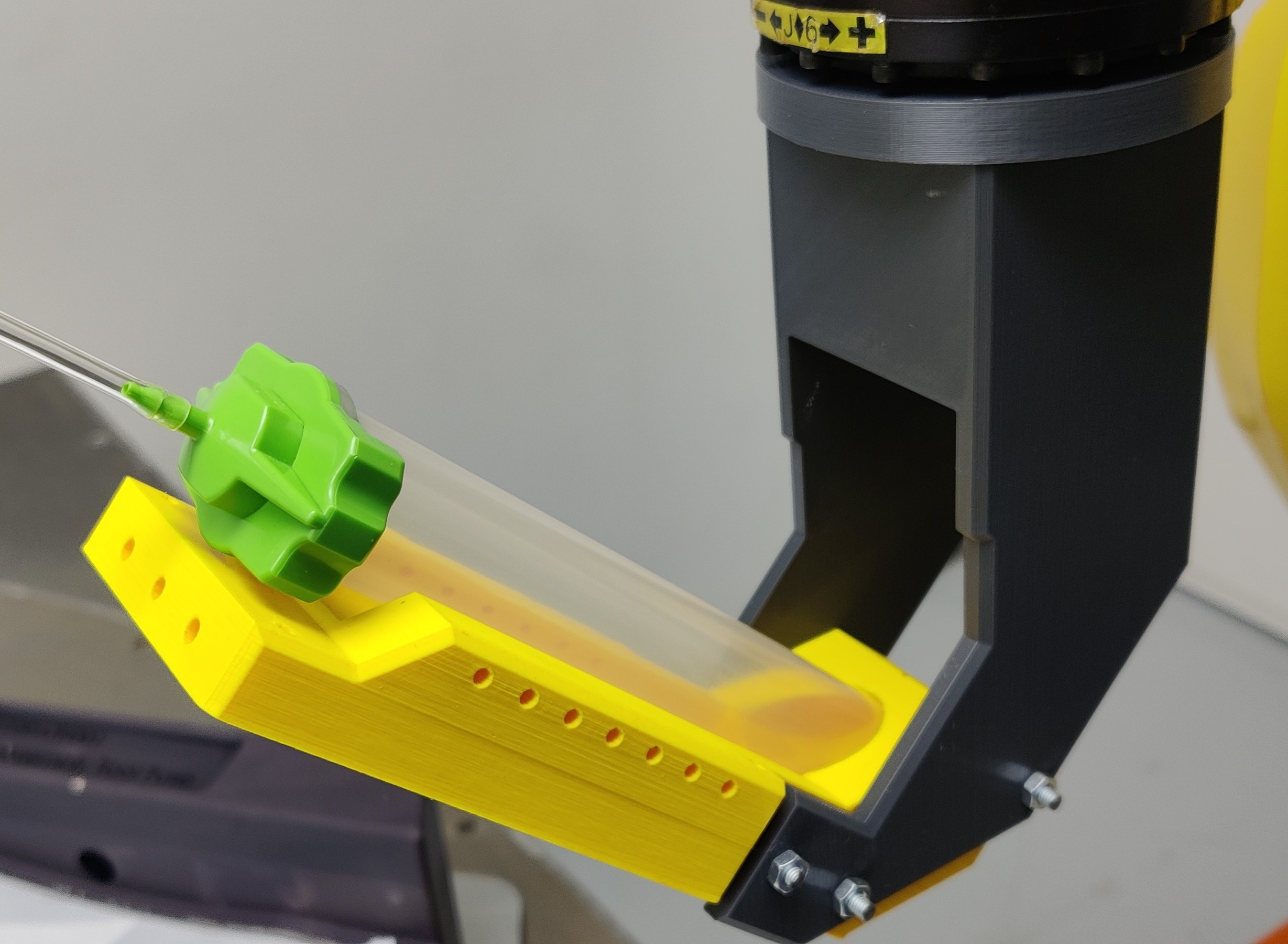
Figure 5: End-Of-Arm-Tool
Module 2.3 (Bonding system – Adhesive regulator)
To make sure a consistent and correct amount of adhesive is dispensed, a regulator has been put in place. This regulator is the Fisnar DC100. The regulator regulates the amount of air pressure that is put on the back of the syringe (in which the adhesive is placed).
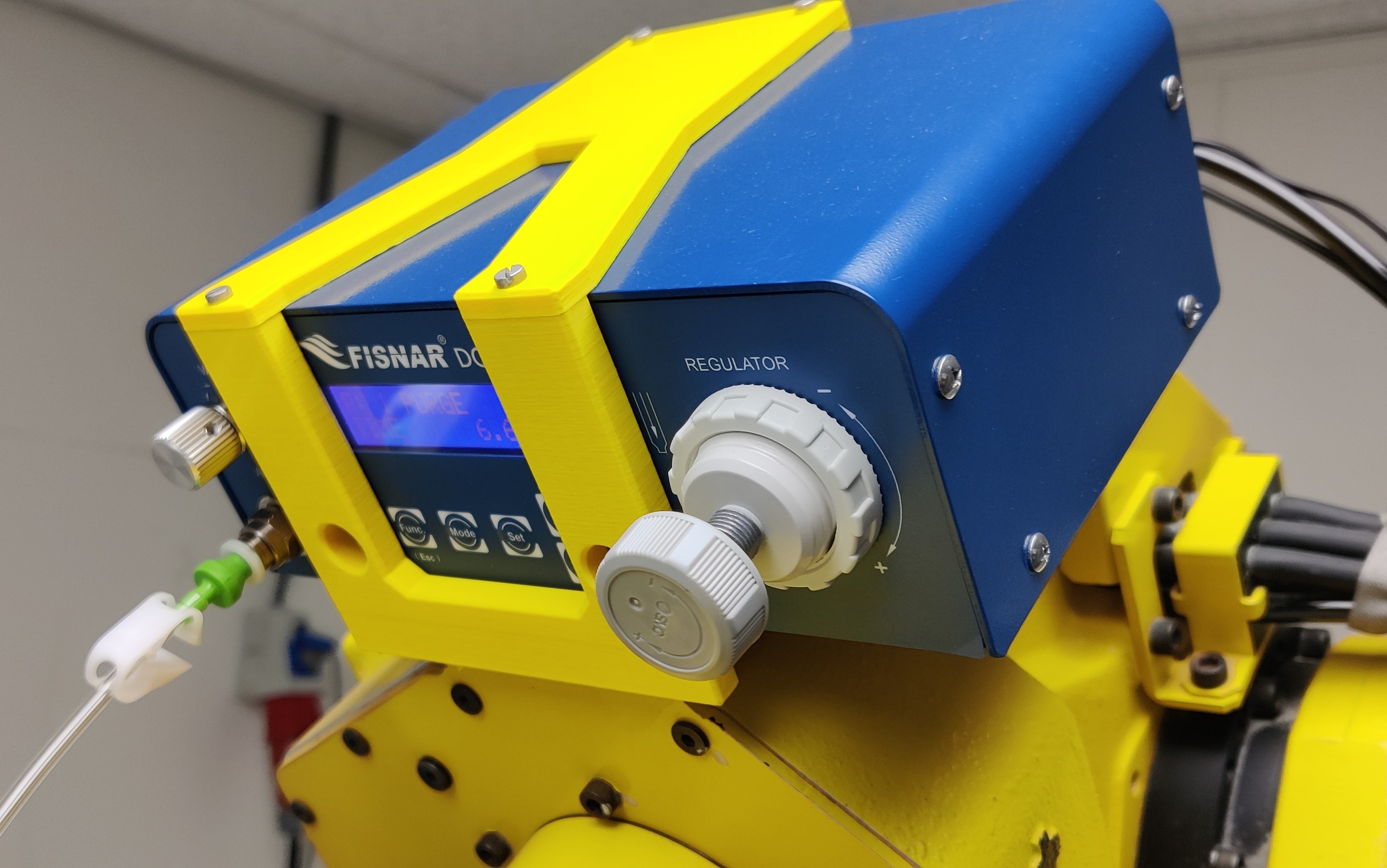
Figure 6: Adhesive regulator (Fisnar DC100)
Module 3 (Inspection system)
The inspection system consists of a Cognex In-Sight 7000 series. This is a smart camera which means the inspection program runs on the camera itself. The camera detects three things. If any adhesive is placed, if the viscosity of the adhesive is correct and if there are possible air bubbles in the adhesive.
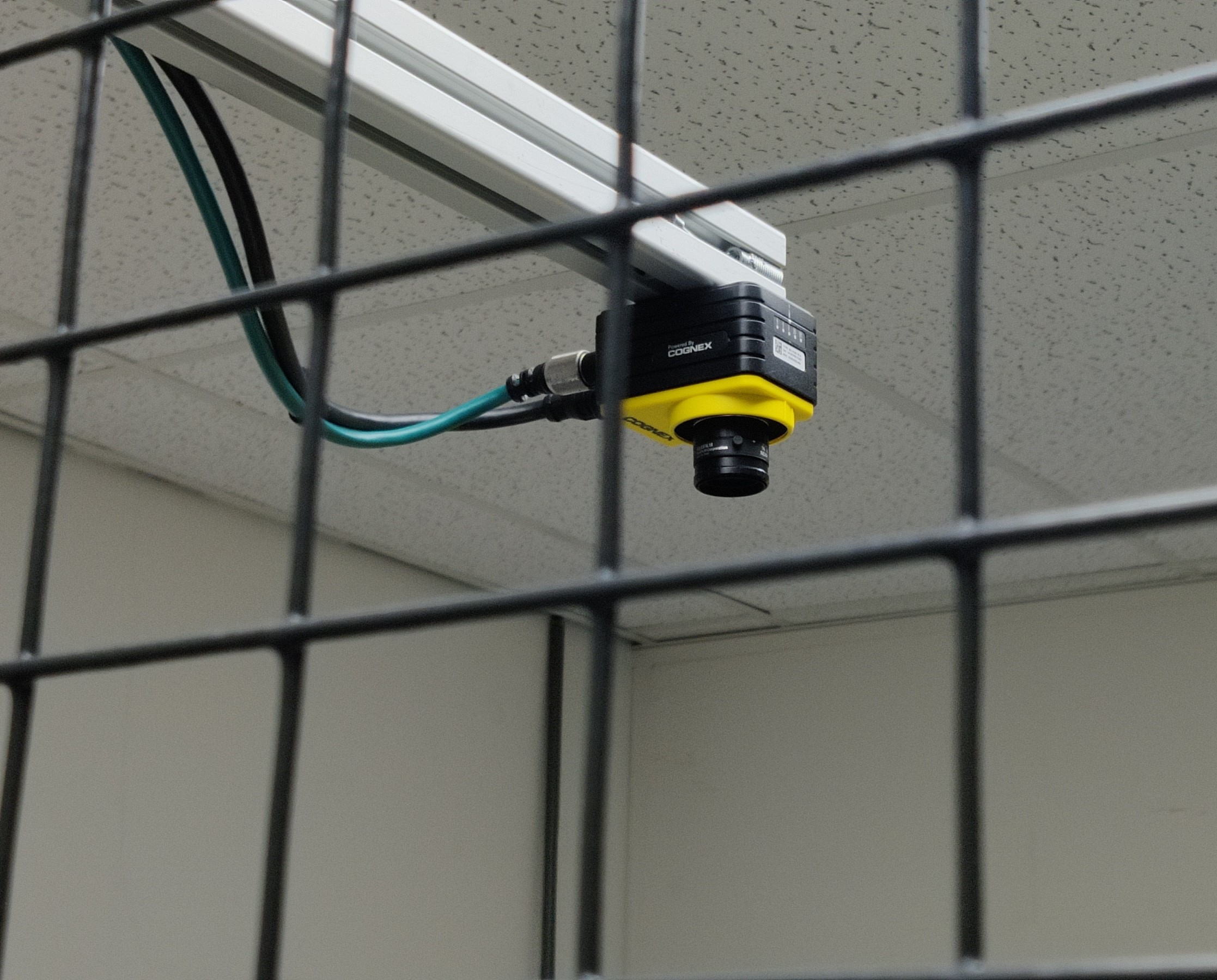
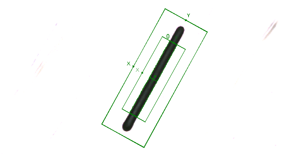
Figure 7: Camera setup (Cognex Insight 7000) Figure 8: Inspection program
Module 4 (Communication system)
To make sure the operator can easily control the whole system, a communication system had to be put in place. This is done by using a HMI (Human Machine Interface). The HMI that has been used is the Siemens KTP 400.
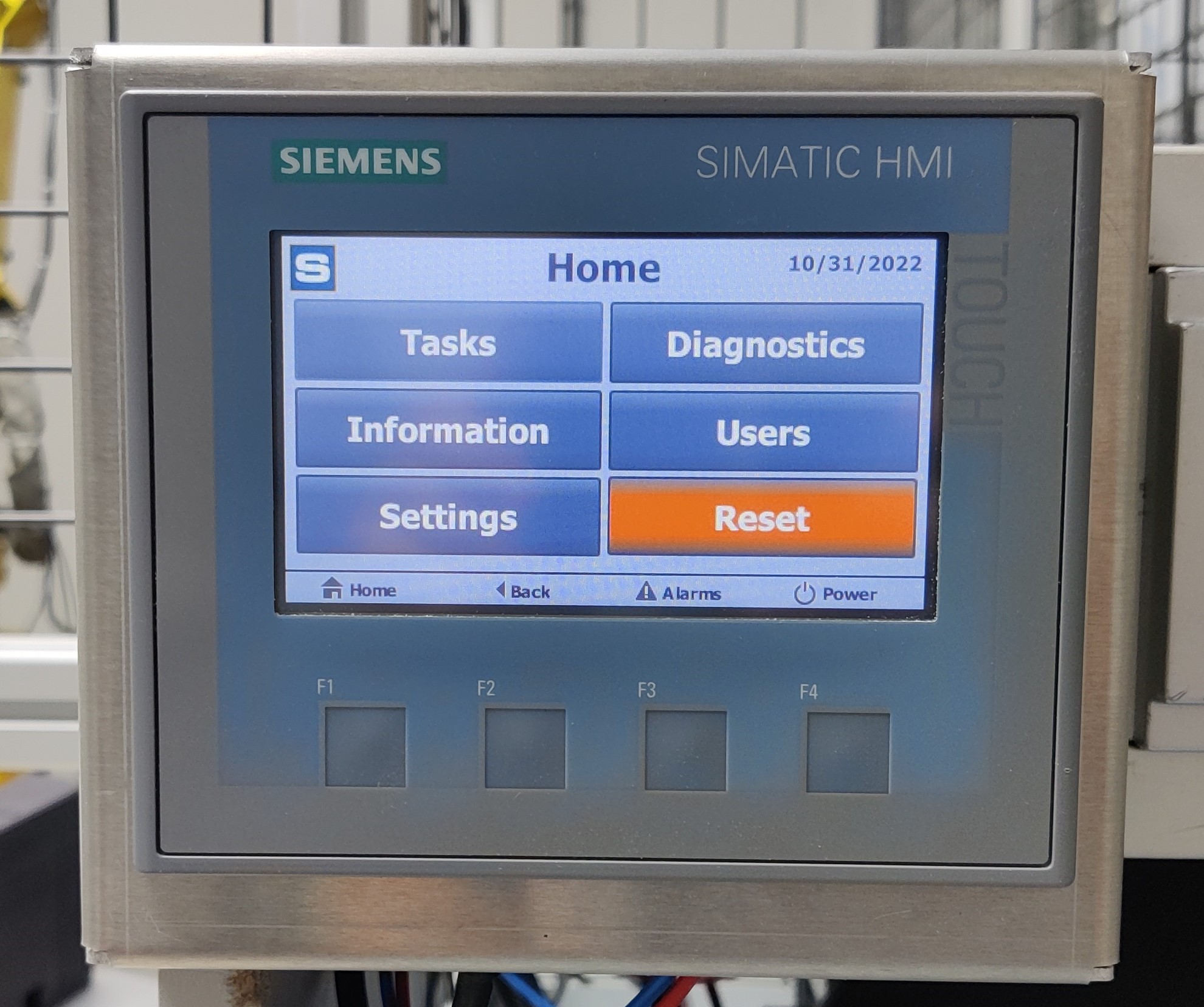
Figure 9: Human Machine Interface (HMI)
Module 5 (Safety system)
The safety system consists of a safety fence, and safety switches around the system. To make sure the rotary table only rotates when no one is working on it, the operator has to push two buttons (one with each hand).
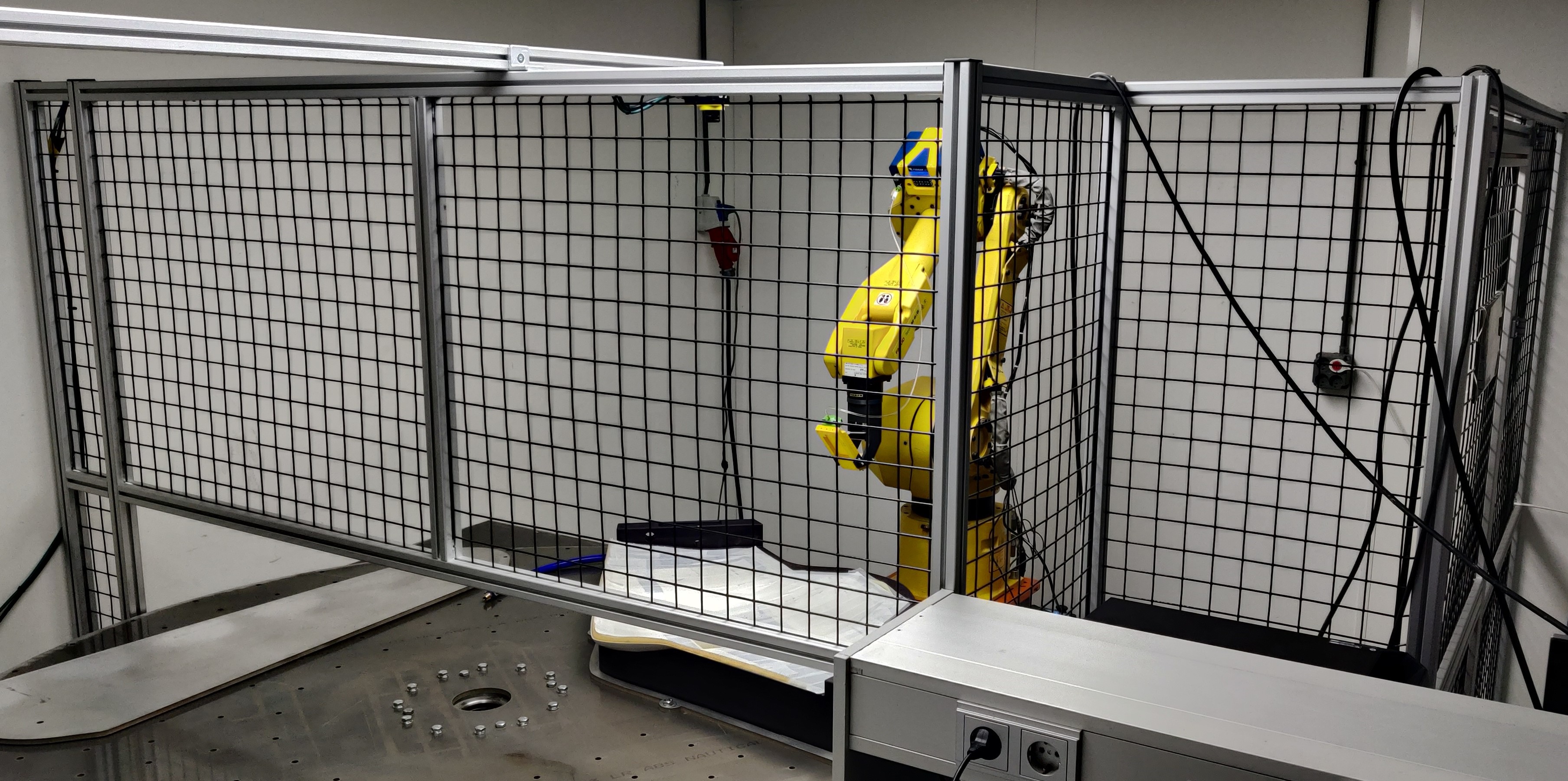
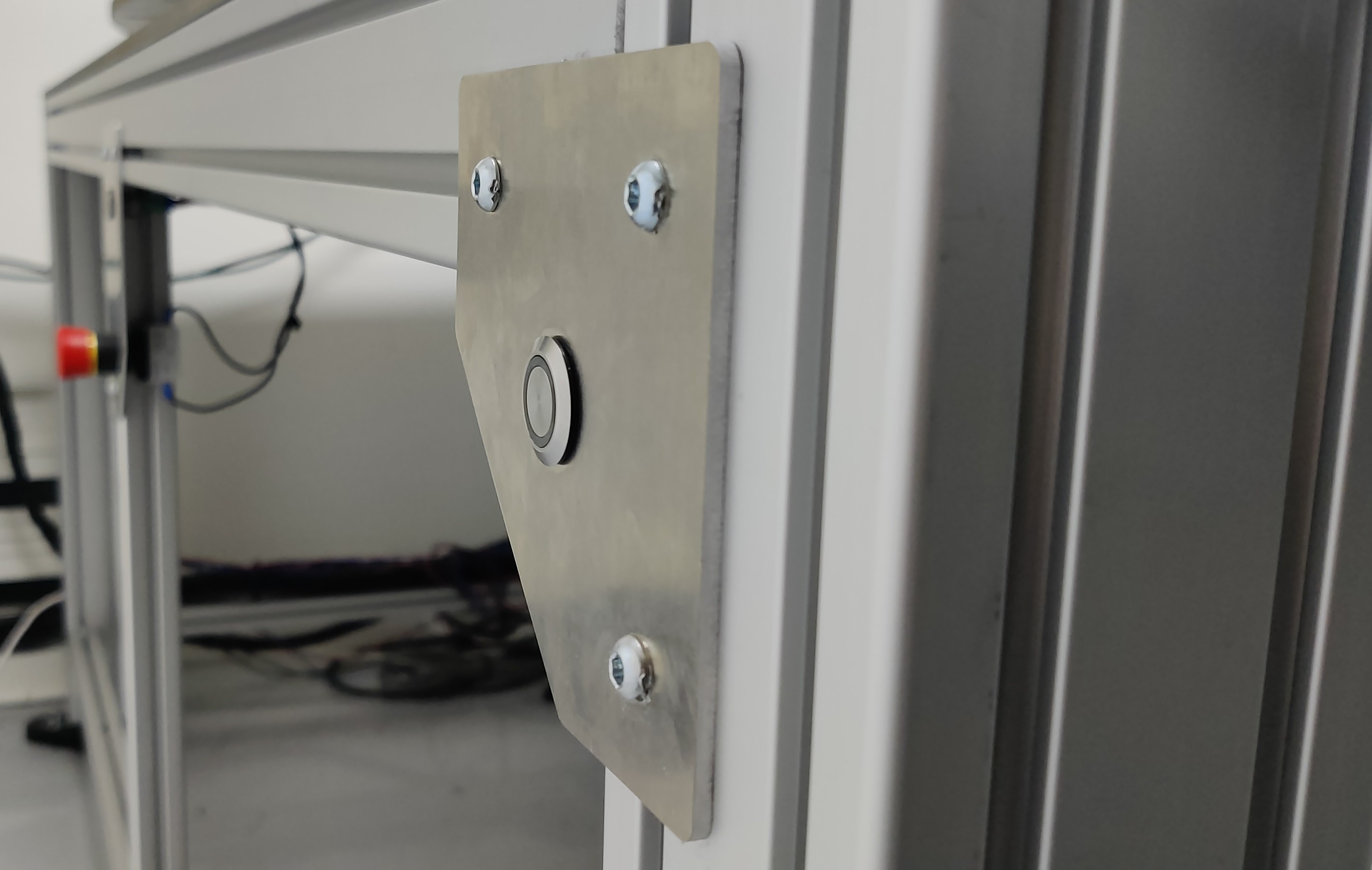
Figure 10: Safety fence Figure 11: Safety buttons
Main decisions
Throughout the project a lot of choices had to be made. Because of the short timeframe and lack of a programmer, we decided to contact experts to help us make the correct decisions fast. We optimized our framework with Item, build a communication between the robot and the SIEMENS PLC with Fanuc, chose our camera setup based on advice from experts, etc.
We also chose to make each part in our system stand-alone. This allowed us to work on different parts of the system simultaneously. This was a necessity due to the short time span of the project.
Conclusion
Overall we are very pleased with the progress we have made in only six weeks and just three students. We have build a platform from which all the parts can be bonded in an efficient and precise way. Scabro Innovations B.V. has given us a lot of freedom to build the system we think is best, and has provided us with the support and resources required.
Recommendation
In its current state, the End-Of-Arm-Tool is not production ready. Also, not all the parts can be bonded at this time. The current vision system is also very expensive so a more affordable vision system is advised. In consultation with Scabro Innovations B.V. and the minor, we will tackle these problems and more in a follow-up assignment.