Automated sleeper assembly
Grimbergen Industrial Systems, Alphen a/d Rijn
Students: Tim de Bondt, Jasper Klerks, Aleksi Mutru, Tim van der Voort (2022)
Project scope
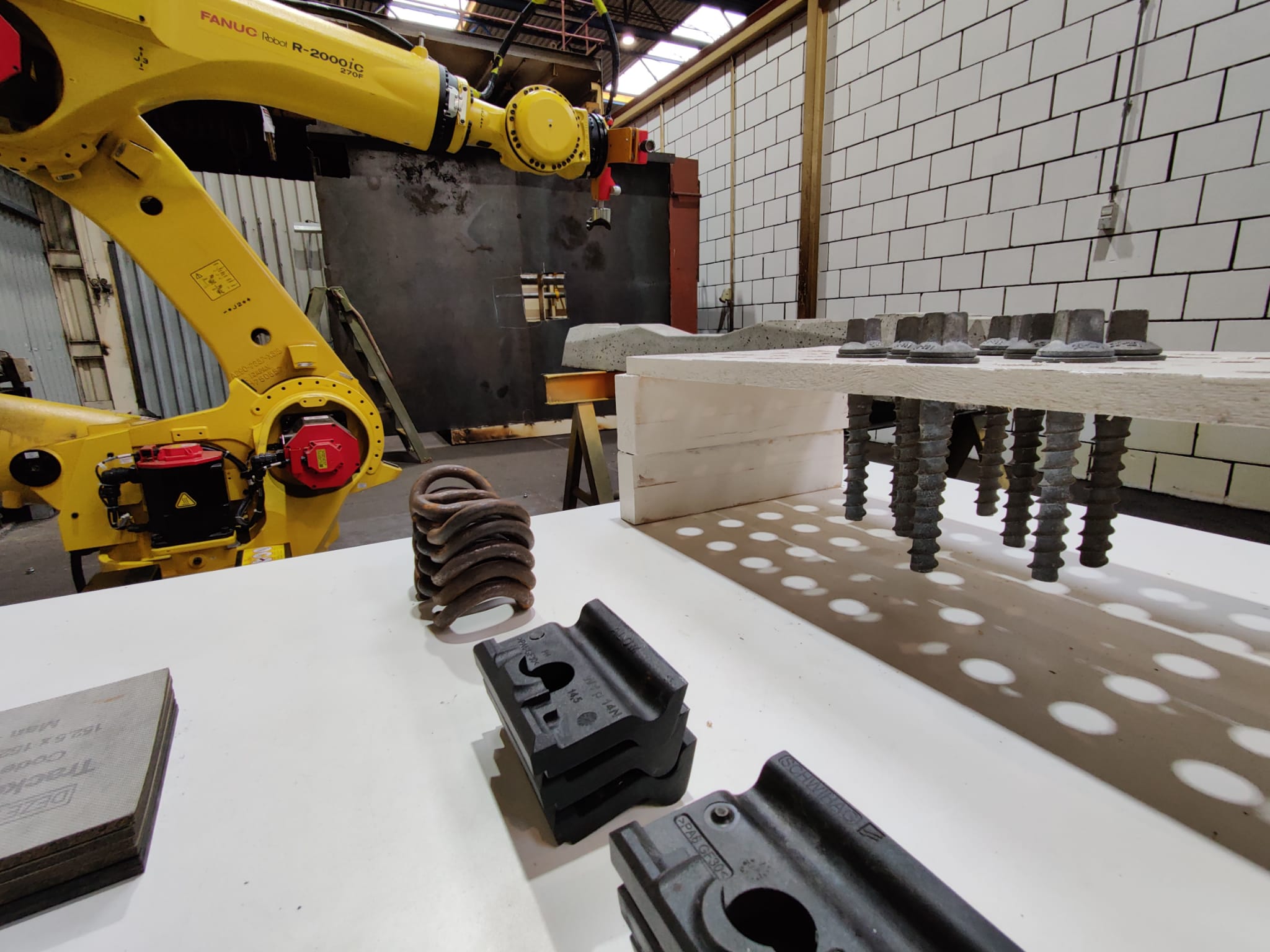
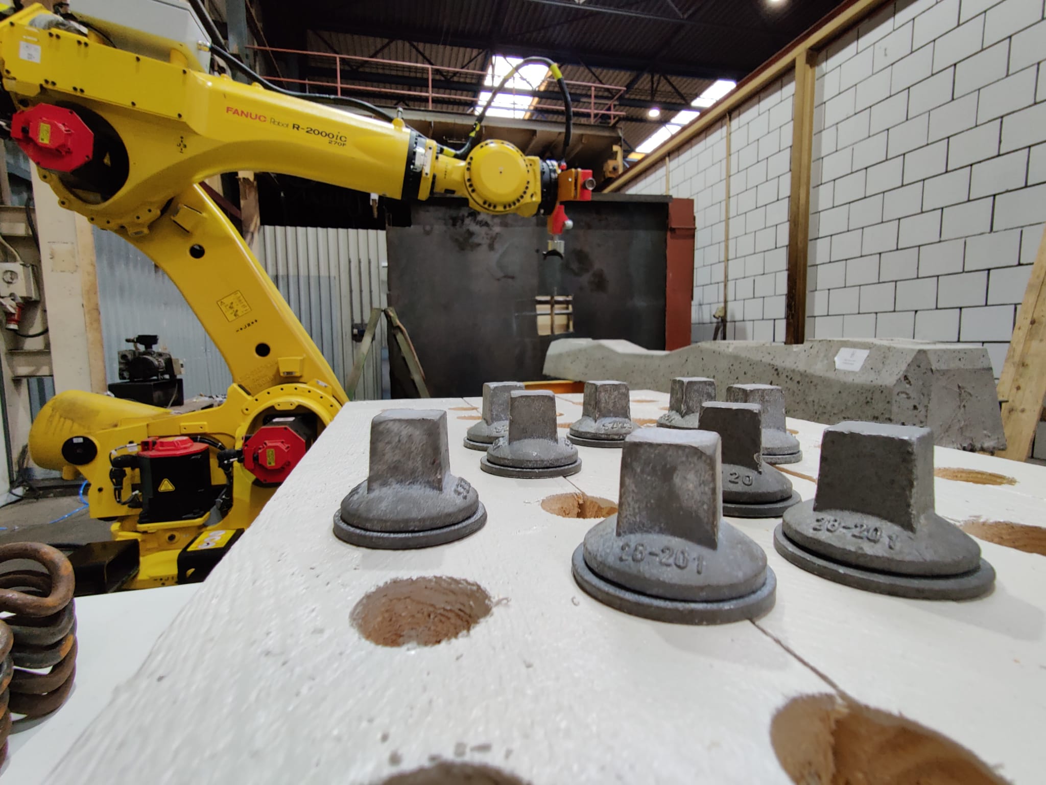
Grimbergen had set out a project which asked for the automation of the assembly of railway sleepers. These railway sleepers need to be pre-assembled prior to being mounted to the on-sight railway tracks. The sleepers are made out of concrete and they need to be pre-assembled with standardized plates, springs and bolts.
This is a process that is normally executed by two workers by hand, with the help of tools. This is a very monotonous job and due to a general staff shortage it is very difficult to find people that would want to do this. Therefor it would be valuable to be able to automatically assemble the railway sleepers within 1 minute and preferably within 50 seconds of each other.
Our solution
During this project we have developed a way of assembling these railway sleepers using a Fanuc R2000ic f270 robotic arm. The robot is able to fully automatically assemble the sleepers, which is the goal for the prototype if implemented in the future.
To accomplish this we have stumbled across a lot of problems. Since the parts are not in fixed places we have used vision based software to locate and pick up the parts. Some of the parts are magnetic and could therefore be picked up using an electromagnet. Other parts are picked up using vacuum suction cups.
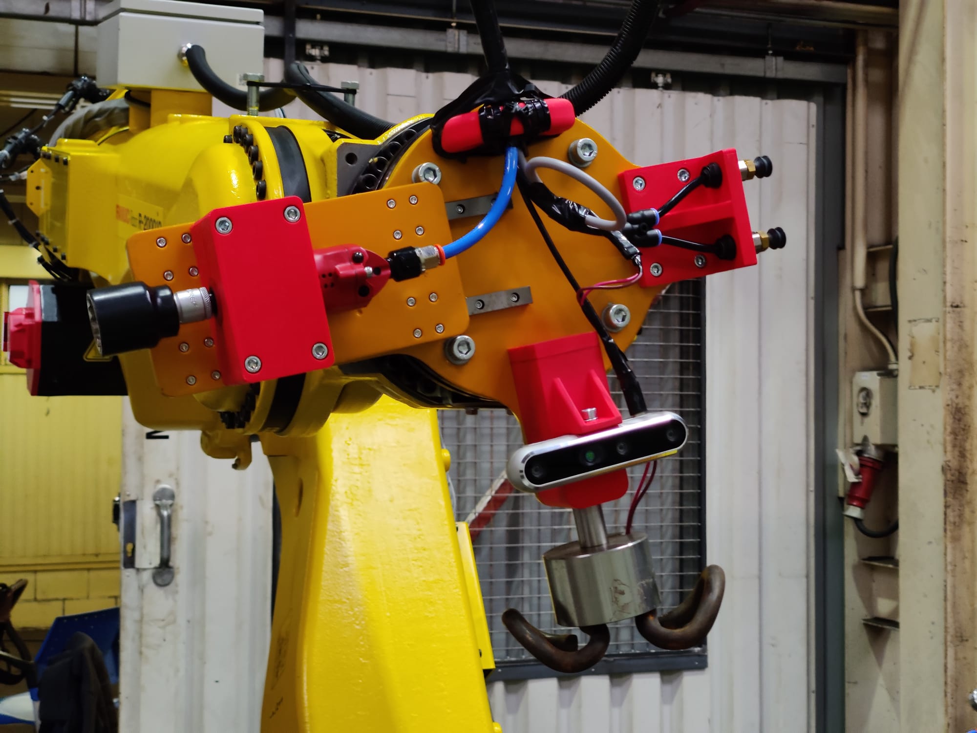
These tools are located on the end of arm tool of the robot. This end of arm tool is shown in the picture above. It contains a large electromagnet, suction cups and a pneumatic impact wrench. In order to safely pick up parts, the magnet does not have a ridged connection to the robot. Instead, there is a spring used to give everything a bit op play.
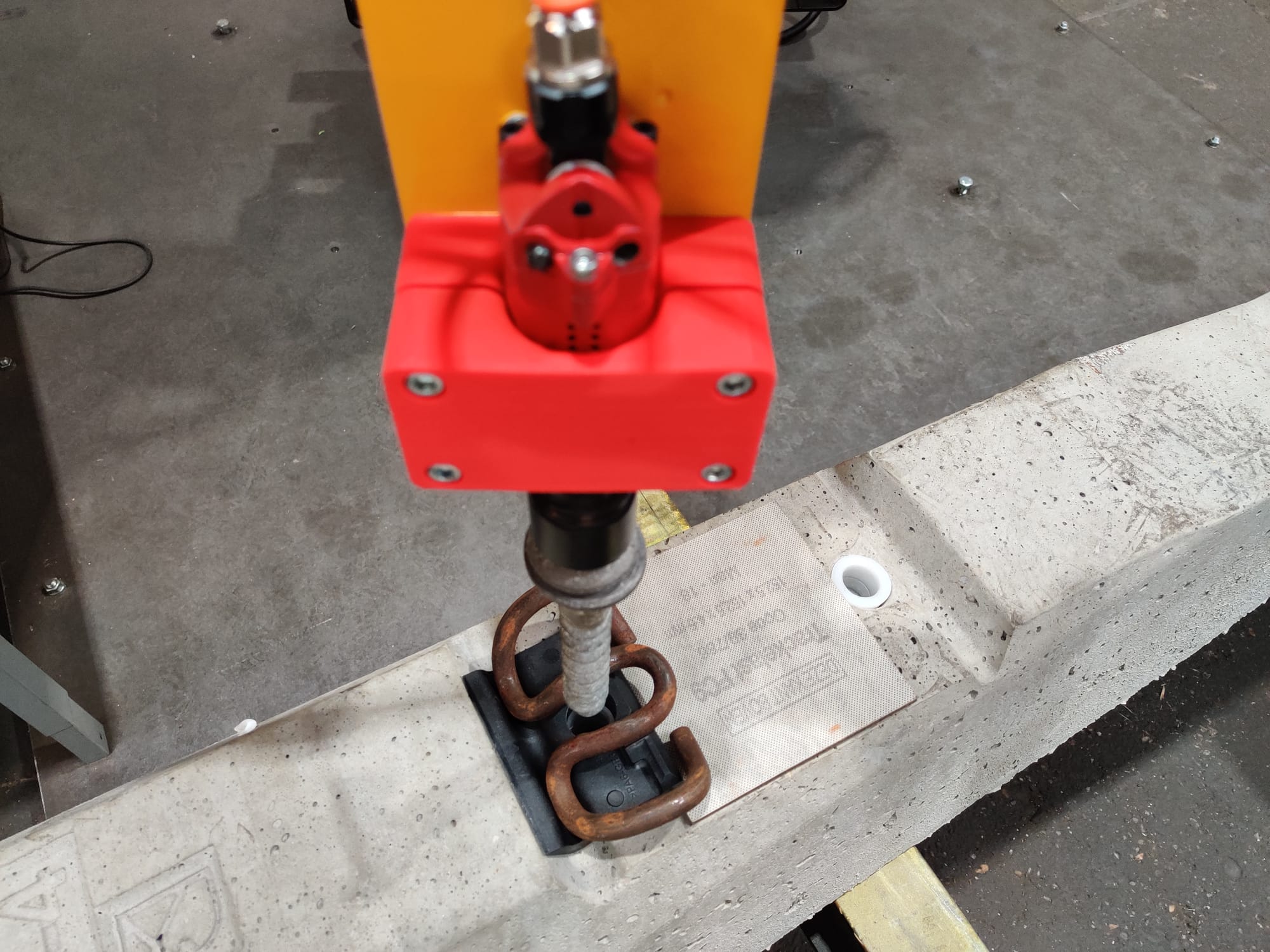
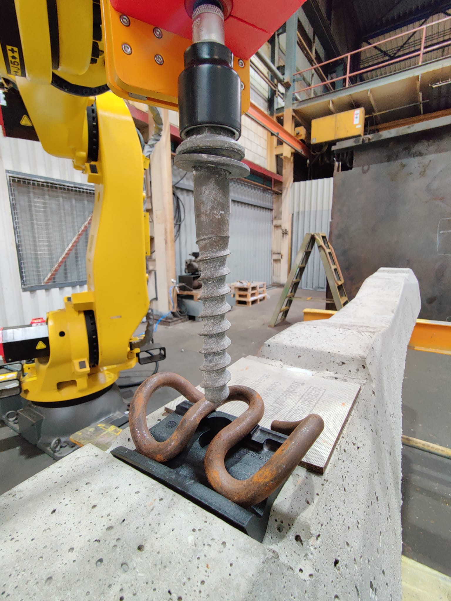
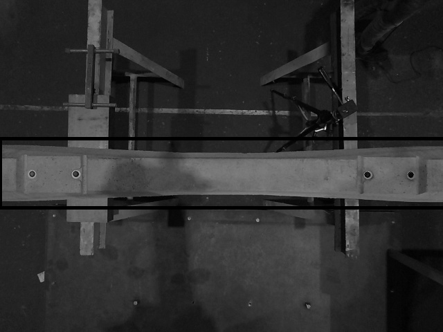
The location where the parts need to be placed is also determined using the same vision based software. After the robot has received it’s coordinates it will move to the desired position and lay down the parts in place.
When the parts are in place the bolts need to be put through the parts and driven in the sleeper. These bolts are driven in using the impact wrench on the end of arm tool, a signal is then given that the assembly has been completed.
The robot is controlled via a graphical user interface (GUI), with standard start and stop functionalities. In addition to that, information about the current robotic movement is printed in the GUI. Because of this GUI, workers now know what the robot is doing, and if it is going as planned or that parts have to be delivered to the robot again if they are empty.
All communication between different media is done via Robot Operation System (ROS), in which all files are linked and depending on each other. For using the end of arm tool, a PLC is used to activate the impact wrench, suction cup and electromagnet. Pneumatics are controlled with Festo valves, which are mounted in an electrical box on top of the robot.
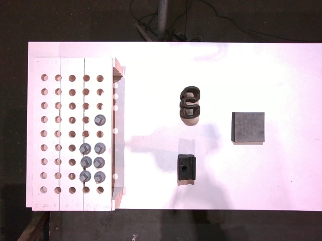
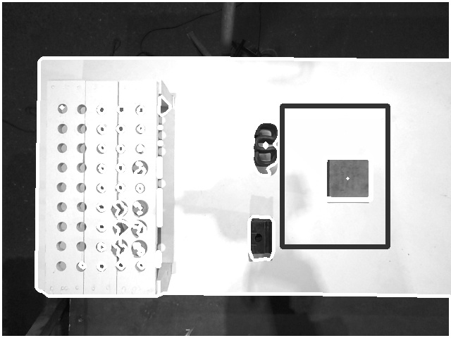
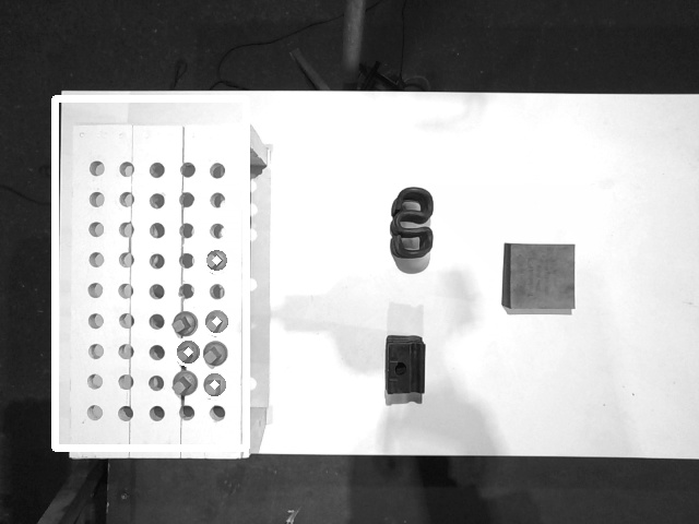
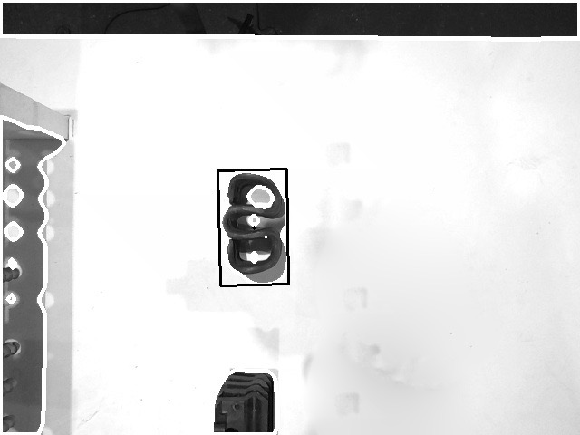
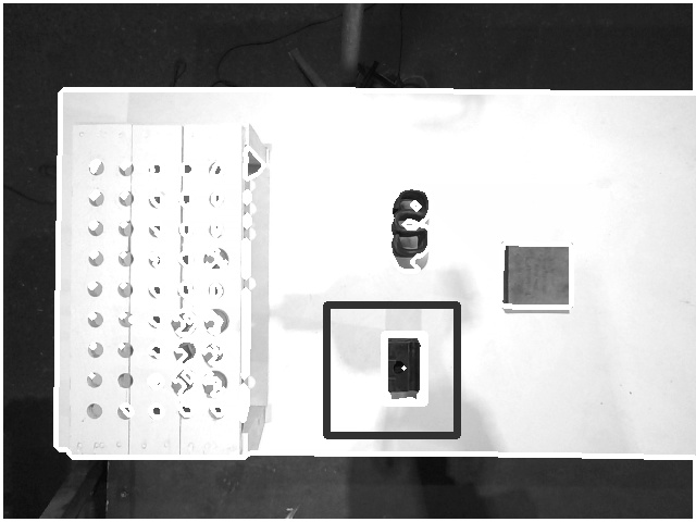
Vision
The robot uses Vision to determine which parts to pickup and where to place them. The camera which is used is the Intel Realsense D455 camera. This camera has stereovision and a depth sensor to determine the Z axis of the robot end of arm tool. Pictures of the Vision processing can be found below.
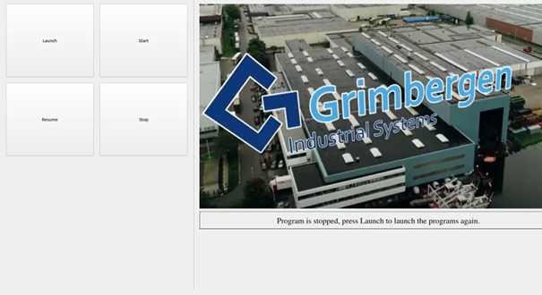
Graphical User Interface (GUI)
We used a GUI to control the program which is running on the robot. It consists out of 4 buttons which can launch the robot, start the execution of the program and resume between al the robot steps. A safety button is included to stop all communication and executing to and from the robot.
Important decisions
During the project we had to make several important decisions about our way of working. First of all was the scope of the project. We chose to work with scope additions. This meant that, if the project was going better than planned, extra steps could be taken to let our prototype be more of a real situation. This however, was not the case and no scope additions have happened.
Furthermore, we had major problems with the ROS setup and accurate control of the robot. Therefore, we chose to do a clean install on the company laptop, which worked very well. The root cause here was that there was almost no space left on the laptop, so files were not written right. Another major decision was the way our file structure had to be made. We had a lot of freedom in it, but it, of course, had to work with ROS. We chose that one of the team members was responsible for thinking out a logical layout of the files, and how we could connect them with ROS and the robot.
Another good decision was to ask for help when we needed it. First of all, we didn’t want any help because we wanted to find out things our self. However, after being stuck on ROS for two weeks, we had to call for help to make the project deadline. In the next project it is really important to get help as soon as we need it, because it wastes allot of time when you are stuck on topics that are really difficult for the project team.
Acknowledgment
We want to thank Grimbergen for this project and all the resources they provided for us. We have learned allot during the project and gained allot of new knowledge about the working area of robotics. All this knowledge will certainly help us in the future and coming projects. It was a tremendous experience to be able to work with such an industrial robot.