Automated welding robot
Grimbergen Industrial Systems, Alphen a/d Rijn
Students: Tim de Bondt, Jasper Klerks, Tim van der Voort
Project scope
Due to the shortage of good welders Grimbergen has set out a project which asked for the development of a welding robot. This robot has to be able to create a 3D model of the part that is layed down on the welding table. This will give the user the ability to define a weld in the 3D model. Based on that information the robot has to weld on the exact place.
Our solution
During this project we have developed the welding system using a Fanuc R2000ic f270 robotic arm. The robot is able to model and weld the part which is on the welding table with the speed that has been given in the Graphical User Interface (GUI).
Our solution had multiple requirements. The system had to be able to:
- Weld different objects on the welding table
- Have the ability to set the speed of welding
- Set two points in the GUI in which the weld will be made in between
- Compare the scanned 3D model with the object on the table
To meet the requirements, we choose to make a Vision based welding robot. The robot uses an Intel Realsense D455 stereo vision depth camera, which scans the object on the welding table and converts it to a 3D model in which the user can select welding points via the Graphical User Interface (GUI).
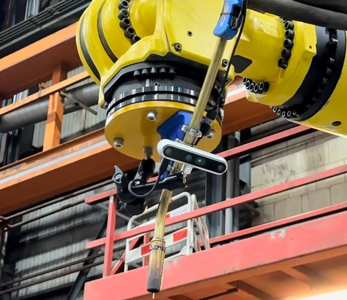
For our solution we choose to 3D print a bracket which holds the welding torch. The camera is mounted on the welding torch with support of a small camera arm, seen in the picture below. Although the bracket and camera are close to the torch, heat is not an issue due to the length of the torch.
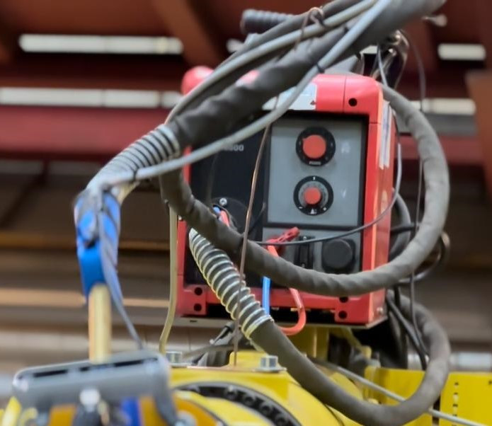
The fanuc R2000IC is a large robot, therefore we used a seperate wirefeeder to mount on the robot. The wirefeeder is shown in the picture above.
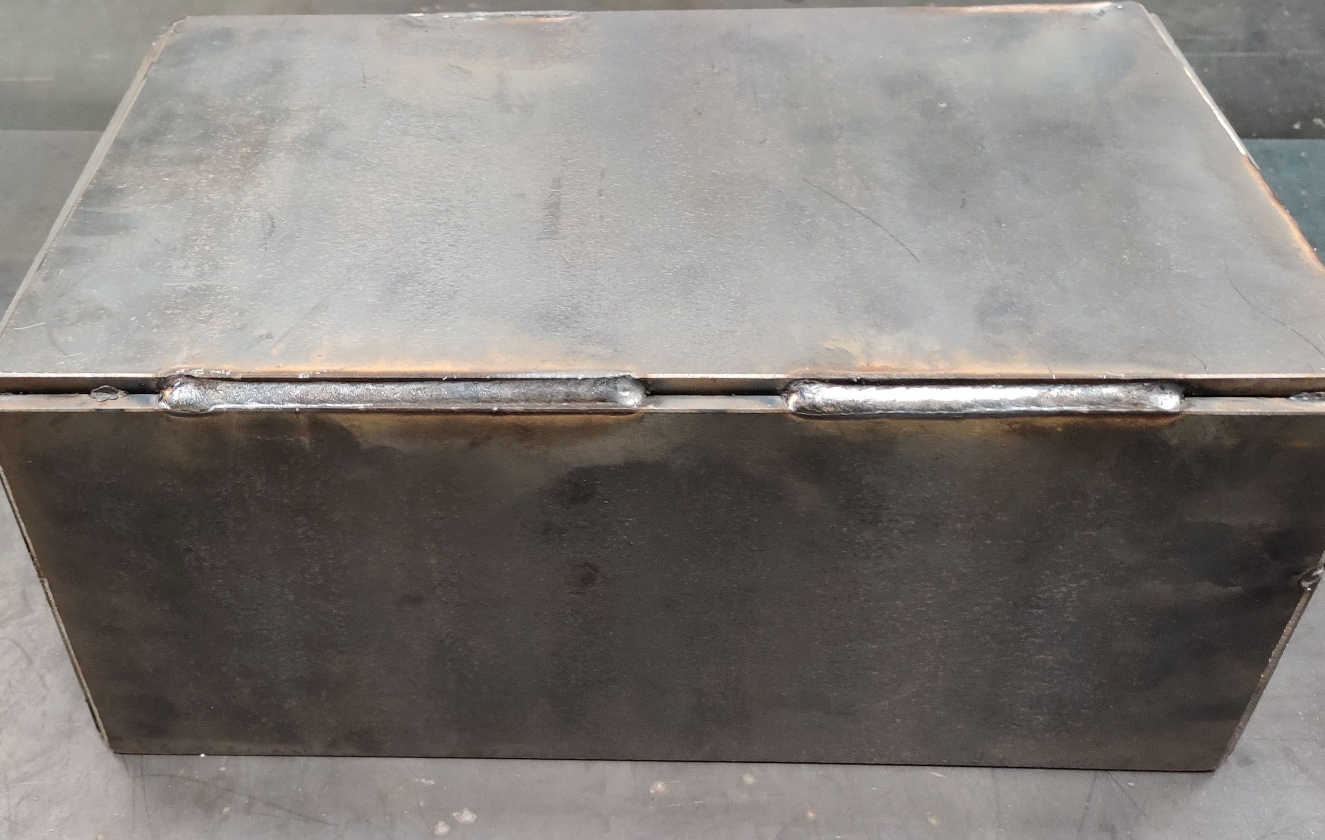
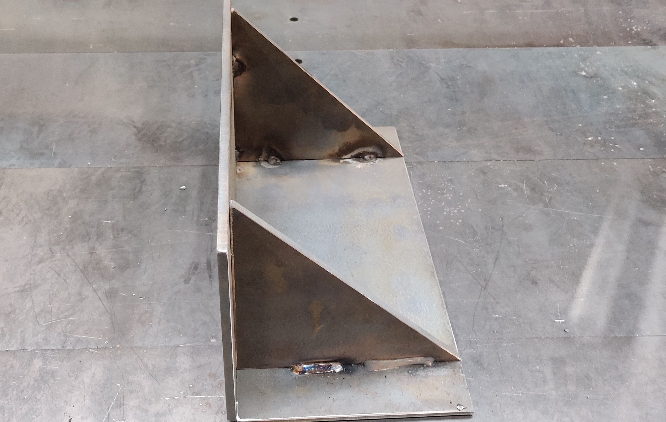
Using the current Intel Realsense camera we get accurate measurements of parts with a minimum dimension of 100x100x50 mm (length x width x height). The welds that are currently possible are straight welds of any size based on the settings given on the welder. The images below show some objects that have been welded by our robot.
Pointclouds
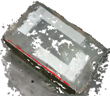
We created a Vision system for the robot. This system creates 10 point clouds in a 180 degree circle around the object on the welding table. After the point clouds are created, they are merged together based on point overlapping with machine learning. The coordinate system is setup based on the first point cloud which was taken. Those point cloud coordinates are then calculated back to robotic real world coordinates based on a rotation matrix. A picture of the pointcloud with a welding line is given below.
Graphical User Interface (GUI)
We used a GUI to control the program which is running on the robot. It contains several buttons and settings to create an optimal weld.
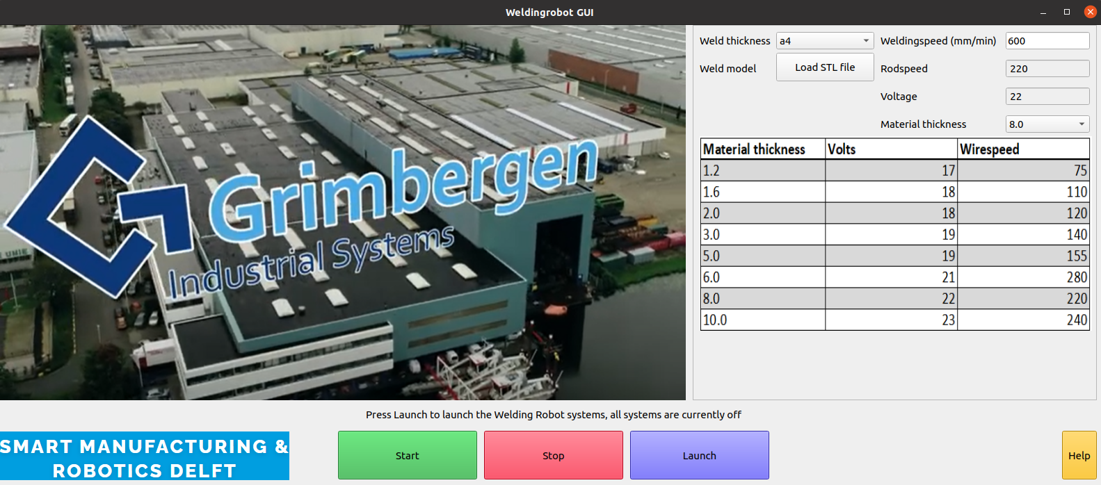
The launch and start button are used to activate ROS and the Python code. Next to that a stop button is found. This button is included to increase safety for the operator and the soon to be welded part. This button can be pressed if a human error is made during the creation of the weld points in the point clouds. A help button is included to provide the operator assistance if needed.
To optimize welding, the GUI is providing different weld settings. It is possible to enter the weld thickness, weldingsspeed, rodspeed, voltage and material thickness. The weldingspeed will be calculated back to robotic motion during welding. A graph is included to help the operator with finding the best settings.
As a safety measure, a compare function is included. The operator is able to enter an .STL model of the to be welded object. After making the point clouds, the scanned 3D model is compared with the provided .STL model, and an accuracy score is given back to the GUI if the system is not certain the object on the table is the to be welded part.
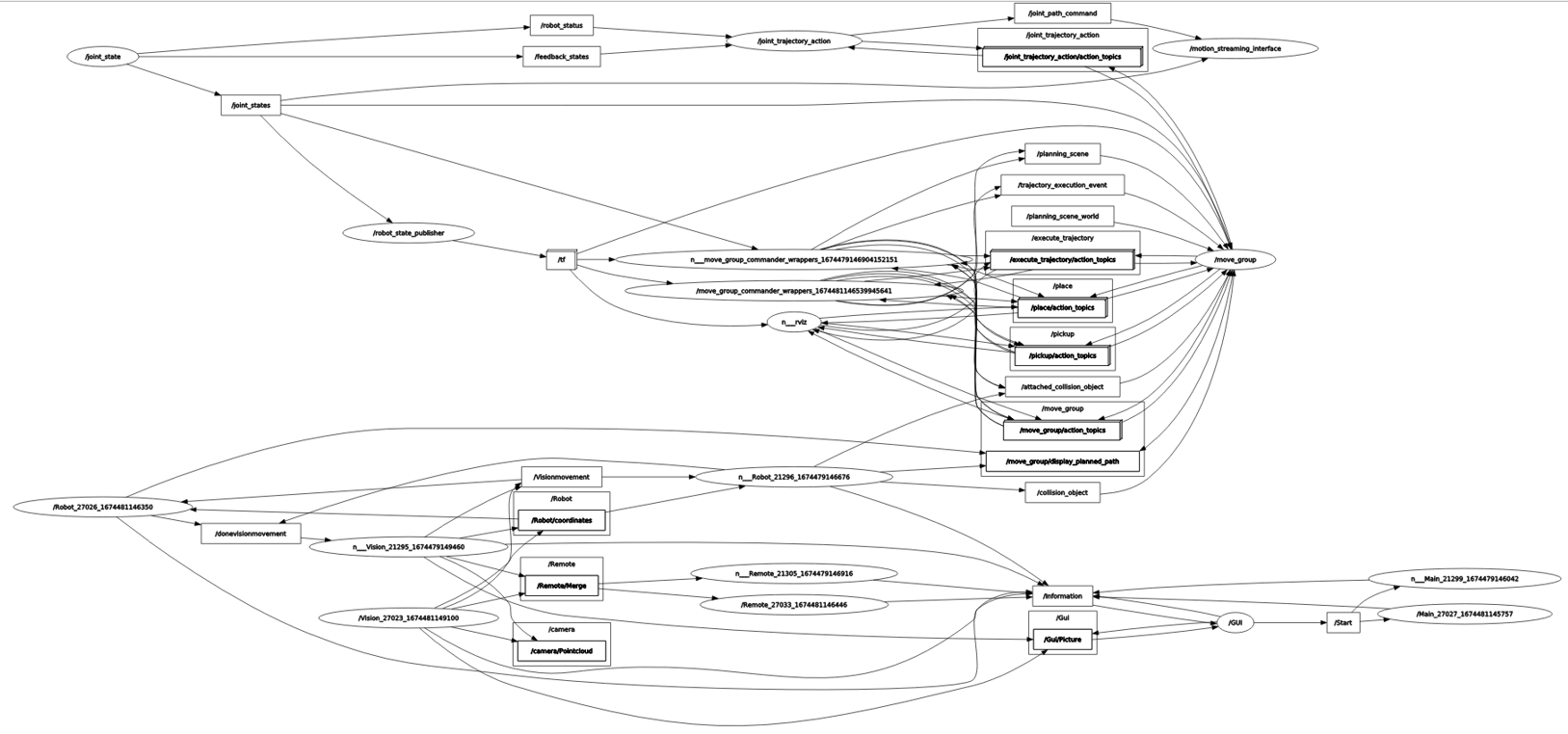
ROS
All communication between different media is done via Robot Operation System Noetic (ROS), in which all files are linked and depending on each other. For using the welding torch, a PLC is used to activate the trigger of the torch via a relay. The publisher en subcriber nodes are visualized below. Server-client relations are not visualized.
Important decisions
During the project we had to make several important decisions about our way of working. First of all was the scope of the project. We chose to work with scope additions. This meant that, if the project was going better than planned, extra steps could be taken to let our prototype be more of a real situation.
Our automated welding system is a prototype. Grimbergen will further develop this system to an industrial level. Due to the quality of the Intel Realsense, we now had minimal object dimensions of 100x100x50 mm. We have strongly advised them to improve the camera quality for an industrial version of the welding system. With a better camera it is possible to improve the quality of the point clouds, and therefore decreasing human error in selecting the weld on the 3D model. We have also advised the purchase of a standard available robotic welding torch. All weldsetting in the GUI, except for weldingspeed, are not connected to the robot. This because a manual welding installation is used in the prototype.
Acknowledgment
We want to thank Grimbergen for this project and all the resources they provided for us. We have learned allot during the project and gained allot of extra knowledge about the working area of robotics and especially ROS. All this knowledge will certainly help us in the future and our further career.