Students: Donizetta Daffa A. H., Ise Kooij, Luc van Eck, Simon Gmeiner. (2023)
Introduction
In an era where electrical appliances and machines become more prominent and important each day, the supply of electricity and charging of batteries also becomes more important each day. You see increasingly more electric vehicles (EV) on the public road but also in industrial areas, cargo ports and airports. In these areas they use fleets of autonomous EV’s that have as much uptime as possible for maximal efficiency of their operation. The uptime is limited by the charging that needs to be done for the EV to operate. Rocsys aims to ensure that EV charging is reliable, seamless, and cost-effective. Rocsys’ innovative approach combines soft robotics, AI-based computer vision, and data-driven services to create a reliable, seamless, and cost-effective charging experience for fleets and consumers.
The current situation
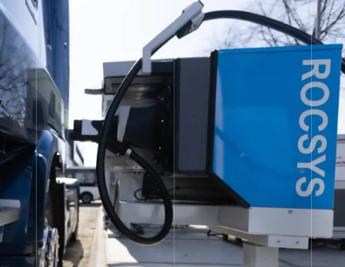
Rocsys uses computer vision as the main guiding principle for their robots. Their vision solution can obtain 3-dimensional data with a single picture from the mounted camera. This picture provides the robot with the information to robustly navigate the plug towards the socket. Their deep-learning-based computer vision algorithms are trained to work under harsh weather conditions such as rain, snow, fog, and bright sunlight.
The current robot they employ is the ROC-1 robot. This robot works with CCS-1, CCS-2, MCS & Euro-Din connectors, but any charger is usable with no system integration. You can mount the charging connector on the system with a specially designed bracket. The system is designed for heavy duty conditions and can be retrofitted to pre-installed chargers.
The problem
The ROC-1 that Rocsys uses at the moment has a limited operation area, using dedicated motion-axes for forward/backward movements, and for horizontal movements. Due to the lack of widespread standardization in charging-plug positions and plug-in angles for electric vehicles, a more versatile robot arm is necessary to serve various clients. Therefore, a larger workspace and more flexible robot are of the essence, which is why Rocsys asked us to create a proof of concept for this specific task.
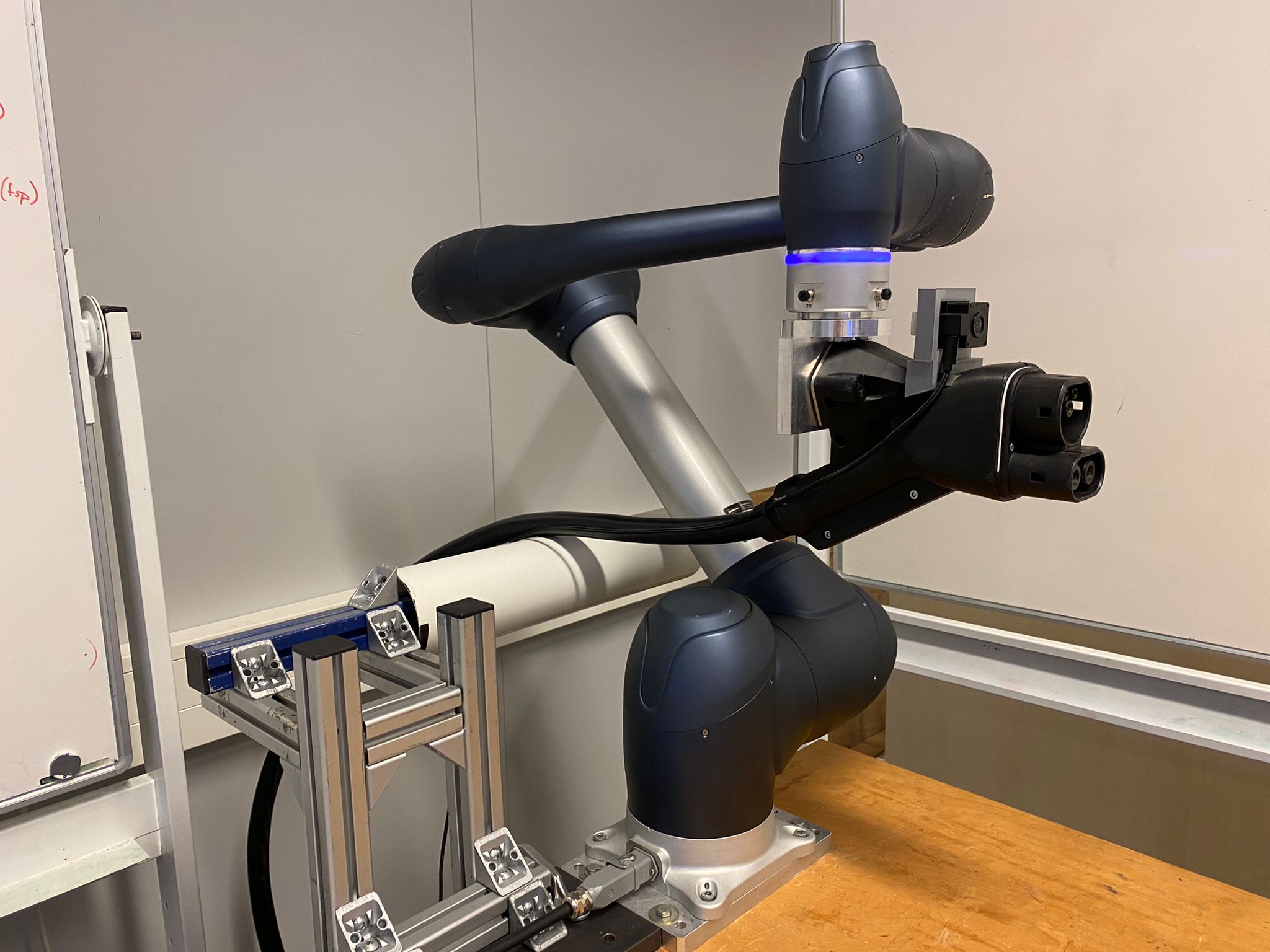
Our solution
For our solution we made a proof of concept (PoC) with a 6-axis collaborative robot, this was the Doosan M1013. This robot arm has a range of 1300 millimeters and can offer a larger work area than the ROC-1. Furthermore, we received a camera from Rocsys to use with their vision software and an EV charge cable type combo 2 (CCS2) to mount to the robot arm.
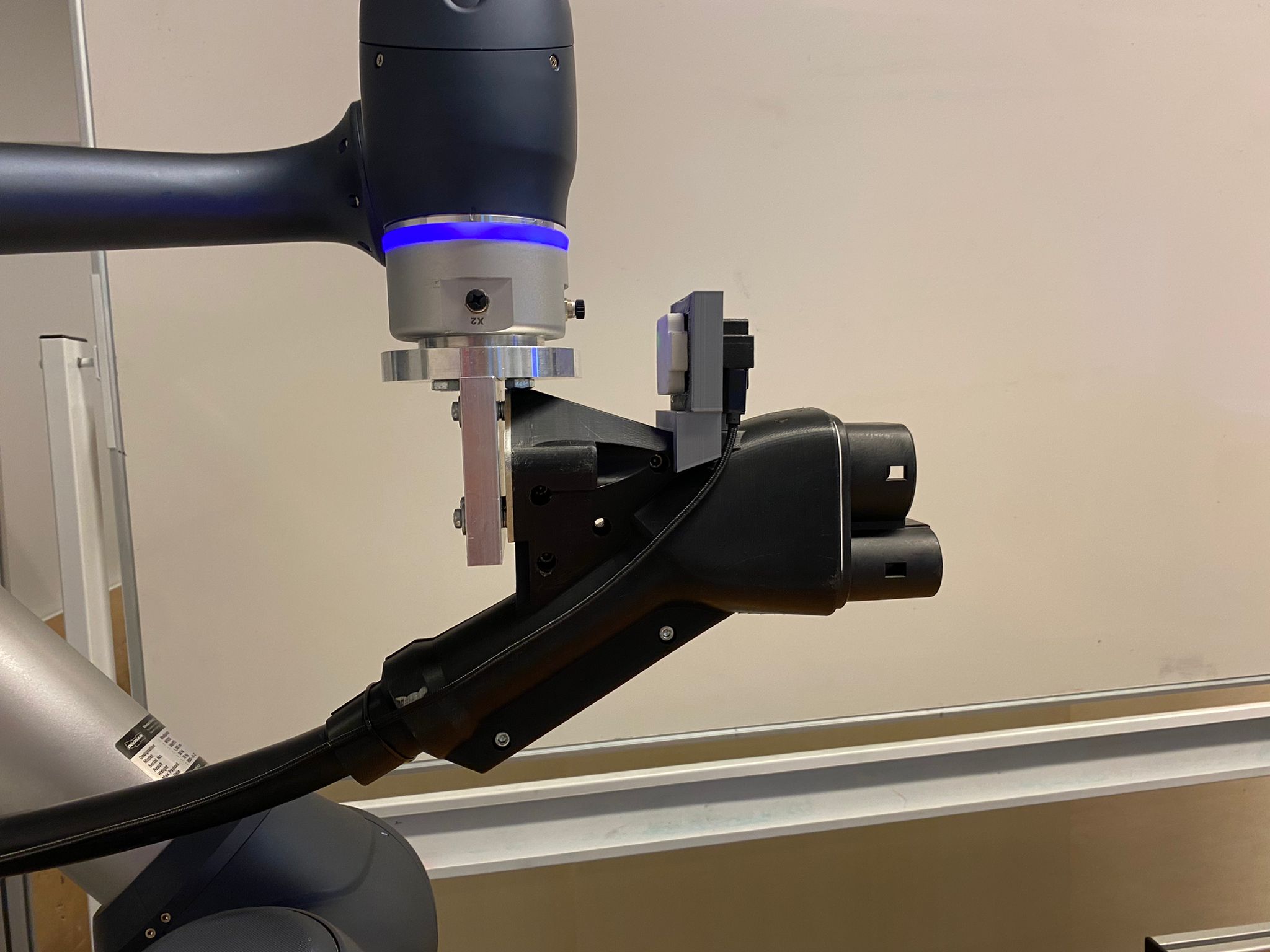
End of arm tool:
The end-of-arm tool (EoA tool) was designed to hold the charging cable perpendicular to the sixth joint of the robot arm. We decided this because of the stress on the robot arm due to the stiffness of the cable. We also chose for the EoA tool to have an in-hand camera on the end-of-arm tool. Otherwise, the robot arm or cable could get in the way when taking a picture of the car socket, this also makes taking a closeup picture easier since the robot arm moves to the socket.
Socket mount:
To be able to test the robot arm we needed a mount to hold the socket which we use for plugging in. This socket mount needs to be sturdy enough to withstand the force from the robot arm and also needs to be easily adjustable so we can test multiple positions. For this we chose an LED mounting bracket and made a metal frame around it.
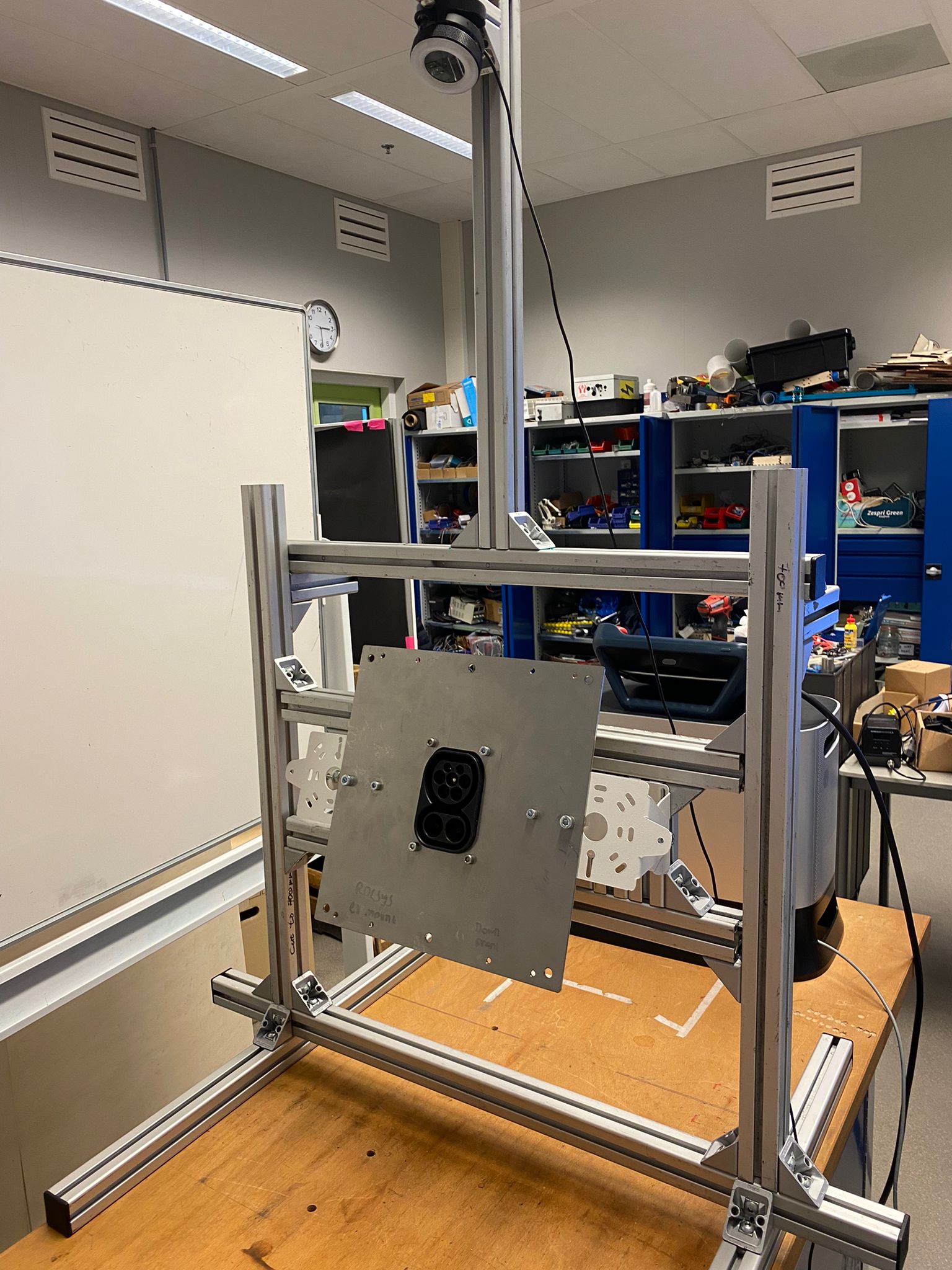
Safety camera:
For user safety we added a camera with a bird’s-eye view that detects people in the robots’ work area using a YOLOV8 detection model. When a person is detected the robot arm will stop its movement to not endanger this person’s well-being. We opted for an object detection program because we need the program to be able to define a difference between the robot arm and a person to make a correct safety stop.
Cable distribution system:
Our cable distribution system was created to lighten the load on the
robot arm since it can otherwise cause the robot to go into a stop due to the excessive load on the tool. It was a roller that slides over a metal rod but due to hiccups which cause stress on the cable we chose to place wheels on the inside, because of this the cable rolls smoothly over the rod and does not hinder the EoA tool.
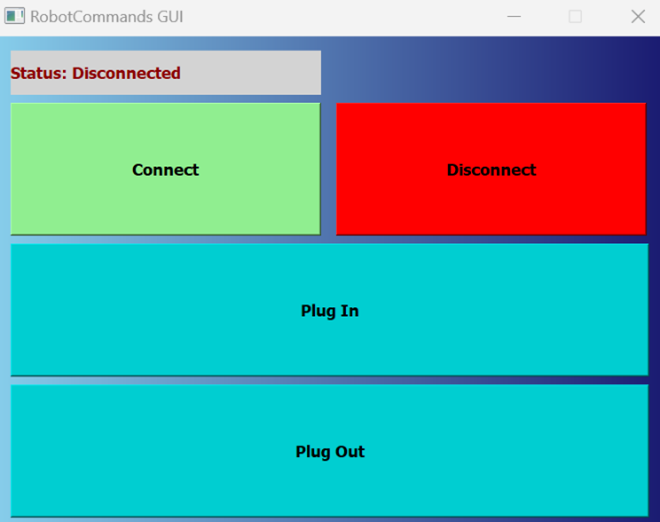
User interface:
To be able to simply use this charging solution we chose to create a user interface that contains buttons for plugging in and out. We also added a status indicator about the currently executed robot task, as well as buttons to connect to and disconnect from our vision server.
Robot movement:
The robot arm will always move to its home position when the user gives a plug-in command. This so the camera has a good view of the socket and can take a picture. The robot arm will then move the end-of-arm-tool and camera closer towards the estimated socket position for a second picture and more accurate socket detection. After calculation, the robot will position itself right in front of the socket and starts wiggling and slowly moving forward to plug in to the socket. When the machine is done with charging, the plug-out sequence will start. Here the robot arm will start by moving backwards out of the socket. After the charger has been plugged out of the socket then the robot arm will move back to its home position.
If at any point in the movement sequence a person enters the working area of the robot, then it will interrupt its movements via a safety stop.
Conclusion
We are happy with how our project concluded. If the socket is in range of the camera and robot, the charger will be always plugged in. But we only tested the setup in very good conditions. To compensate for little inaccuracies in the socket coordinates when in extreme weather conditions, we wanted to use force/stiffness control that the Doosan robot provides. Only the weight on the end of arm was too great to make use of this function. This proof of concept could be improved if a robot with a higher payload was applied so that the force/stiffness control could be used.