|
Project member |
Discipline | Phone number | |
| Mechanical Engineering | +31 6 28948247 | ||
| Mechanical Engineering | +31 6 26332593 | ||
| Telecom Engineering | +34 6 08064827 | ||
| Informatics Engineering | +31 6 17251792 | ||
| Deividas Stravinskas | Mechanical Engineering | +31 6 84358127 |
GitHub: https://github.com/syahsuri/suitcase_Factory
The company
Suitcase company Gefken in Den Haag manufactures custom made suitcases and flight cases. With their extensive range of custom aluminum profile cases they offer solutions for every industry and application in packaging, displaying, transportation and specials. The standard suitcases made by Gefken are made from a combination of wood and plastic. These plates are glued to the aluminum extrusions and assembled forming a suitcase.
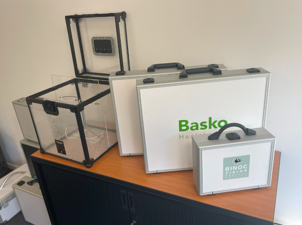
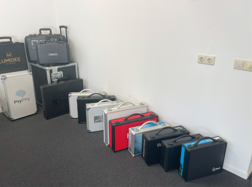
Figure 1: Custom suitcases by GEFKEN Cases Ltd Figure 2: Custom suitcases by GEFKEN Cases Ltd
Original situation
Normally the suitcases are glued by one person using an air pressured glue gun. After the frames are partially assembled the glue is spread out in the grooves of the frames. There are four different frames needed for the assemblance of a suitcase. These frames have different grooves at different angles. The glue used for the cases is high in density and comes in sausage shaped packaging that is put into the glue gun.
Method: the compressed air flows through a controllable valve into the glue gun. The air pushes against the plunger, pushing the glue out of the gun.
Figure 3: Current gluing process suitcase frames
The problem
Gefken Company has a short employee staff so they need to use their employees in the most efficient way. Actually, the glueing task requires a person wasting his entire time performing that job. For the moment, they can do it in that way but, for example, if they want to increase their market demands they would have to optimize their workers as much as possible.
Summarizing, this non-automated process presents a series of notable disadvantages:
- Inefficiency and reduced productivity: This manual process is inherently slower and more labor-intensive than the automated one.
- Inconsistency in quality: Human error is an inherent risk in non-automated processes. Inconsistent glue application and bonding may lead to quality variations, negatively impacting the reputation of the company and customer satisfaction.
- Higher labor costs: The requirement for a significant labor force in manual operations contributes to higher labor costs, including wages, benefits, and training.
- Difficulty in process control and monitoring: Maintaining consistent quality and process control becomes more challenging without the precision and real-time monitoring capabilities of automation.
In conclusion, they had been considering automating this part of the process trying to find the most efficient way for having a smart manufacturing process. Eliminating this non automated task allows the company to use that employee for another task, without being aware of the gluing process. Furthermore, they will make an increase in quality technology and reliability, adapting to this new technological era.
The (automated) solution
The company wanted us to work on automating the gluing process. This process consists of gluing three types of aluminum frames, the ones they use most.
In short, for this task, the employee will place in the table three different wooden plates with the frames inside, selecting the amount of frames they want to glue and wait until the task is completed.
In the next picture you can see our setup for the process, including the wooden plates with the frames, the UR10 robot needed, the camera for detecting the sizes of each frame and the interface for the interaction with the customer.
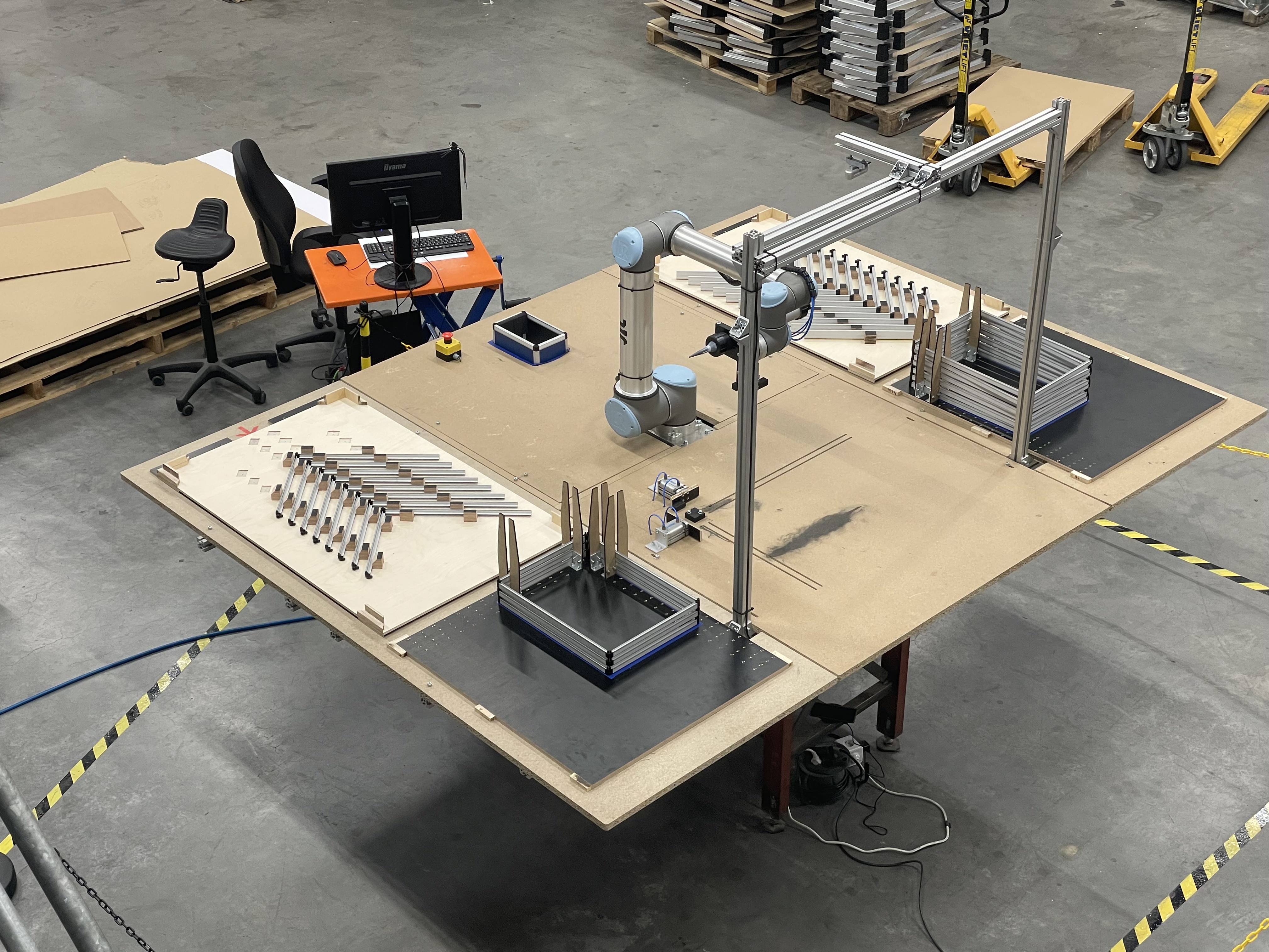
Figure 4: Final robot setup
For this process to be done, we had to work with these software, pneumatic and hand – made implementations:
End-of-arm tools
We implemented an end-of-arm tool based on a gripper and a pneumatic glue gun, after testing with other different types of glue gun. Our final prototype is the next one:
– GLUE GUN – GRIPPER
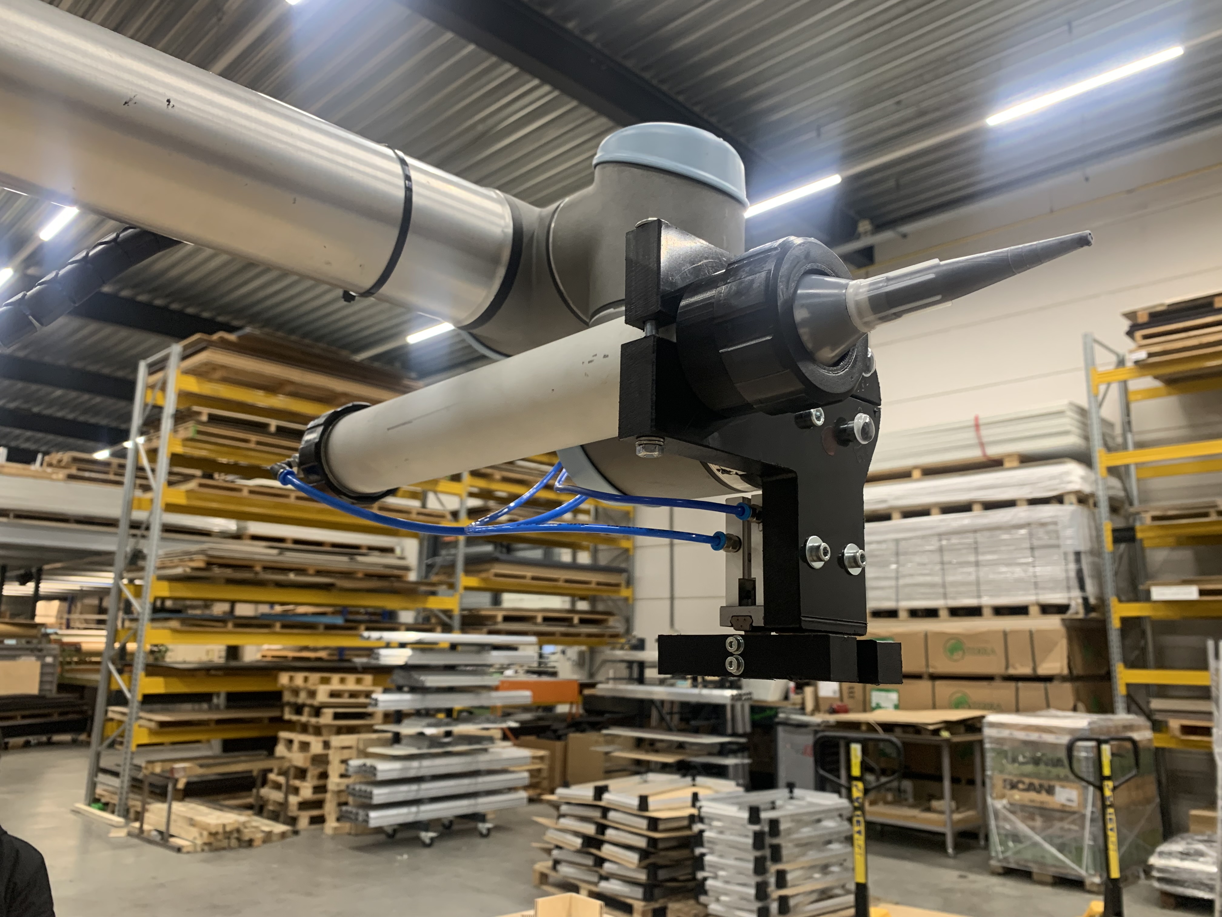
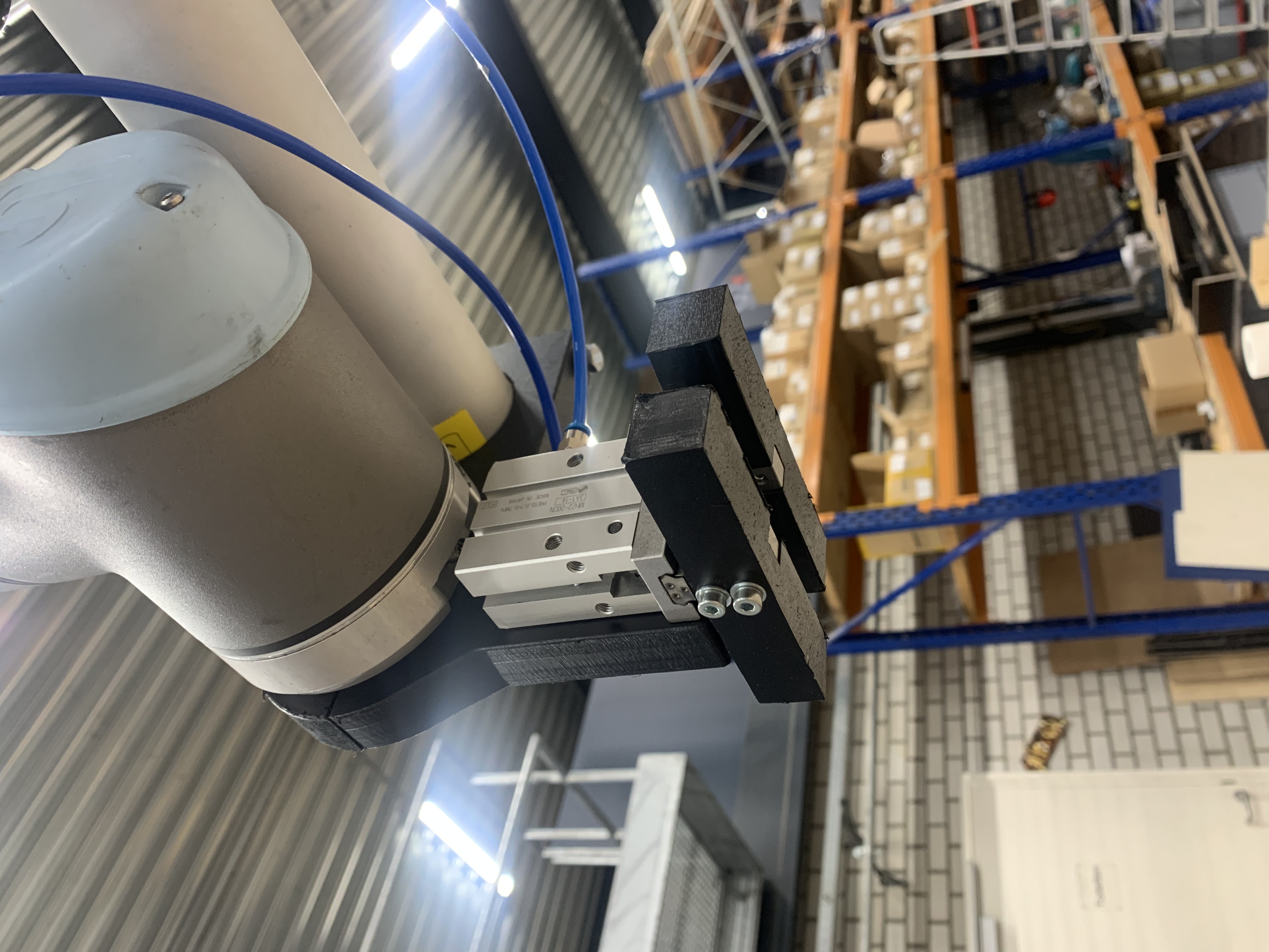
Figure 5: Pneumatic glue gun Figure 6: Gripper
Machine Vision
The vision was a process of trial and error. It continued to fail during the most unexpected times throughout the testing phase. Although at last we managed to set down a stable version that was reliable for 100% of the usages, in which you detect the length and width of each frame. Initially we used a common algorithm from OpenCV named cv2.minAreaRect(). This function, although very powerful and fast, was often unreliable in our situation, causing rotated results and background jigs causing improper rectangles. Our new approach is a custom build algorithm which detects the correct frame sizes in 12 milliseconds while rendering results for feedback within 30 milliseconds.
The customs algorithm determines the fixed origin of frames in the working area. Out of this point, two lines are created, adjustable to the natural bend of the frames. These lines calculate a line of sight (LOS) for each side. For feedback purposes it displays this strip of LOS into separate frames visible on the computer. These LOSs calculate with color detection where a certain frame stops, marked with a red line. It then calculates the size of each LOS by the amount of pixels multiplied by a fixed calibration value.
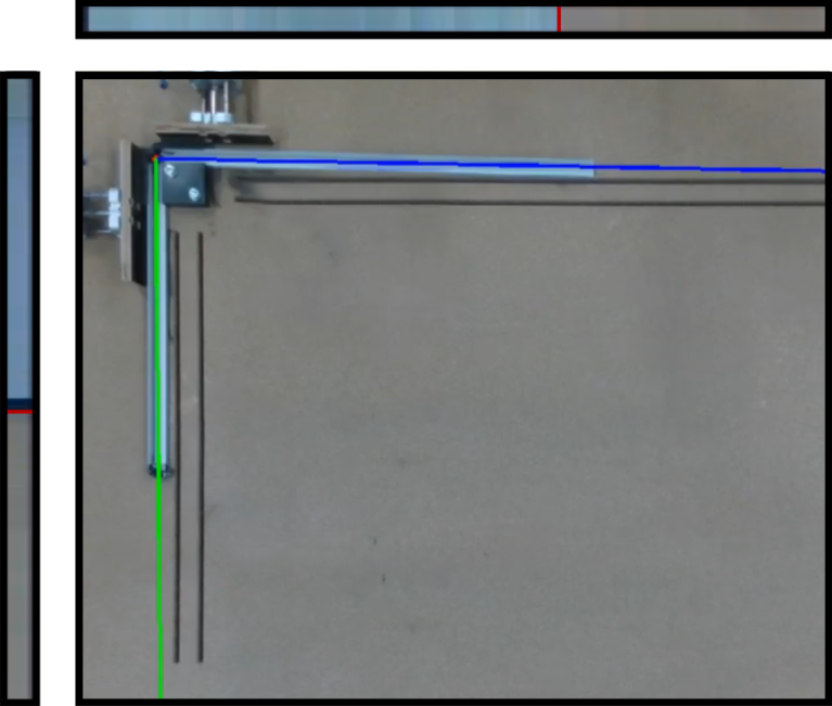
Figure 7: Length detection with machine vision
Communication
For interconnecting the whole process, we needed to have reliable communication between the camera vision part, the robot and the interface. We decided to establish TCP communication between them and as each program is done with different software tools, we had to implement three servers in order to have a good connection. Our final communication setup is described in the picture below:
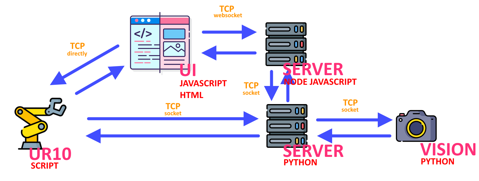
Figure 8: TCP communication
UI
In this process, we need an employee to make decisions, such as the number of frames to glue or when to start or stop. For performing these tasks, we need to establish a User Interface for the company. In our case, this interface has the whole control of the process, with tasks such as deciding when to start, pause or stop, number of frames, performing a gluing inspection or changing the glueing sausage.
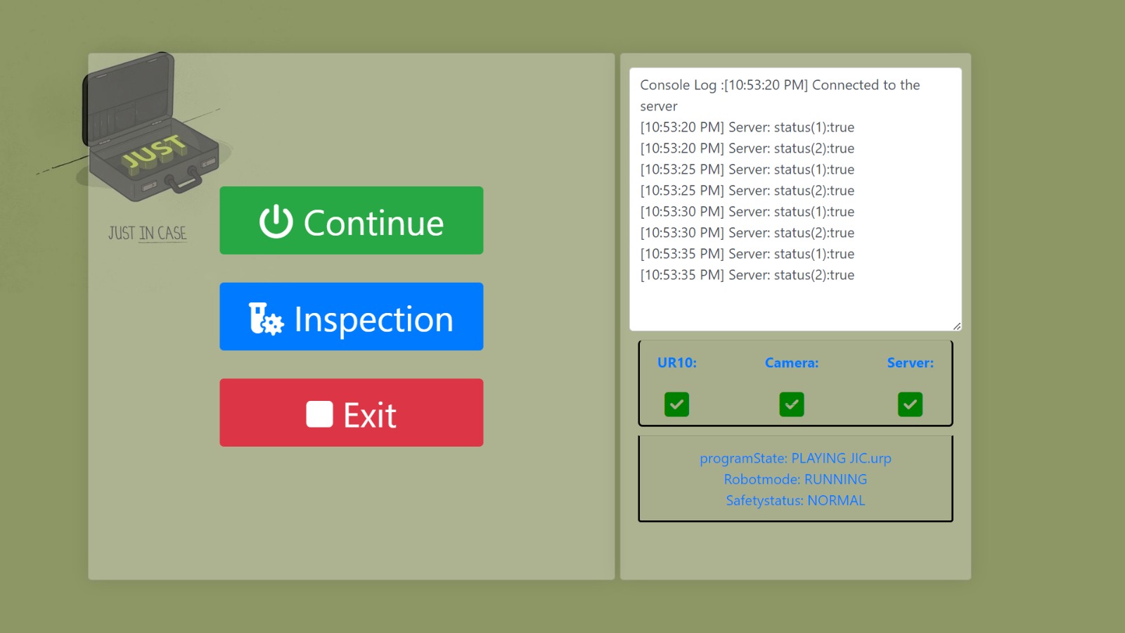
Figure 9: Home screen UI
Furthermore, we have added some visual tools such as a progress bar, the status of the robot, camera and servers, or the number of frames completed, all in an easy and understanding way for the workers.

Figure 10: User input screen UI
Major decisions
Project Scope
The scope of this project encompasses a wide range of dimensions for various frame types. However, this project is delimited to frames falling within the dimensions ranging from 150 x 150 mm to 800 x 600 mm, which represent the most prevalent sizes in the product line.
The project does not include the incorporation of a glue level indicator, which could be an enhancement. Nonetheless, it is noted that a magnetic switch could potentially be implemented for this function. Additionally, the project does only encompass the adjustment of gluing speed as comprehensive process control. Advanced control functionalities such as the regulation of other parameters like temperature and air pressure may be considered for future iterations but are beyond the current scope. This prototype for example exclusively employs room temperature glue, although the option of integrating a heating coil to manage viscosity remains a possibility for future iterations.
End of Arm Tool
The selection of a pneumatic glue gun was made due to considerations regarding glue leakage and the unfavorable center of gravity associated with the electric version. This decision was informed by rigorous testing and evaluation. The project does not involve the use of glue feeding tubes, as they seemed only to be viable with shorter lengths when using this type of glue. Consequently, a direct mount of the glue gun is the chosen approach.
Robot Setup
To ensure precise and consistent glue application, a jig has been integrated into the system. This jig ensures that glueing positions adhere to a fixed set of coordinates. This method is preferred over reliance on machine vision to detect areas requiring glue application. Furthermore, custom frame racks and trays have been incorporated within the pick and place zones. These specialized setup components are designed to consistently deliver various frame types to the robot in a uniform position.
Machine Vision
Machine vision is employed for the sole purpose of length detection, enhancing user experience by eliminating the need for users to manually input dimensions. The use of machine vision for identifying areas requiring glue application has been omitted in favor of a jig-based approach, which is proven to provide greater accuracy.
Regarding the machine vision setup, it is pertinent to note that a bare wooden panel has been chosen over a contrasting background like a greenscreen. This decision is based on the anticipation that the gluing table may become soiled during the gluing process.
Our conclusion
The automated gluing solution significantly improved efficiency, consistency, and overall quality in suitcase manufacturing at Gefken Company. By eliminating the manual gluing task, the company can use its employees more efficiently and adapt to the demands of the market. This project represents a step toward smart manufacturing, enhancing the company’s technological capabilities and reliability in the modern era.