Students: Tim van der Meijden, Lombard de leeuw, dennis van den berg, joeri vos.
About AWL
AWL is a multinational systems integrator that focusses on automation and robotization on both the automotive and machine industries.
Assignment
AWL wanted a cost-efficient generic solution for bin-picking problems. Bin picking is a core problem in computer vision and robotics. The goal is to have a robot with sensors and/or cameras attached to it pick-up known objects with random pose and positions out of a bin using a suction gripper, parallel gripper, or other kind of robot end-effector.
Scope
AWL provided a basic model for the bin picking process, a PVC straight joint. These parts are reflective and have a round surface area, which makes the detection and gripping a bit more difficult.
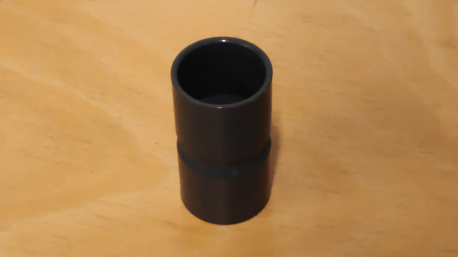
Image 1: PVC straight joint
The provided solution needed to be built with MVTec HALCON in the integrated development environment HDevelop. The cycle time for bin picking one instance of the object must be as short as possible.
Solution
AWL has multiple teams working on different bin picking solutions. They currently outsource a strategy with an expensive setup using an infrared scanner and a large cycle time.
The found solution from our team is constructed from a combination of machine vision, a proper work area layout and a forgiving pick-up method.
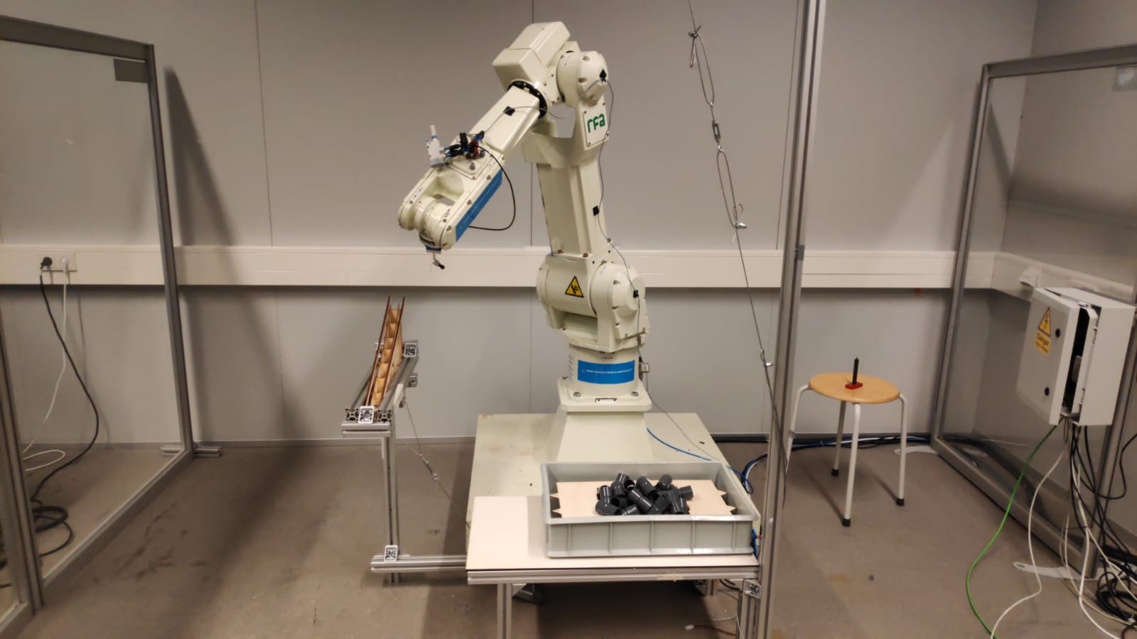
Image 2: The setup
To create a more cost-efficient solution, a simple 2D camera is employed, using preloaded 3D models of the objects. Another plus side with the use of a simple camera is the rather small amount of image data that needs to be analyzed, which has a positive impact on the processing time of the program. Small flaws and errors in the detection are minimalized by the protocol for the pickup .
Vision
Detection
The 2D camera captures an image to be analyzed. Then the image get processed by using filtering techniques to optimize the object detection. A given number of instances and their positions and poses can now be found. When the accuracy of an found object is high enough the position and the pose will be send to the robot for pick-up.
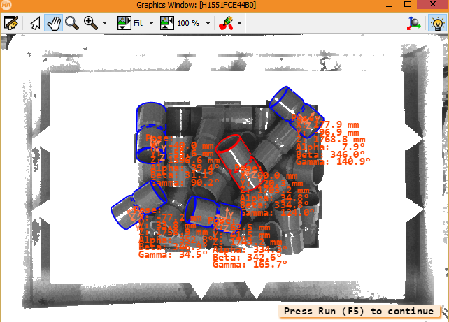
Image 3: Object detection
Filters
Only the gray values from the frames of the camera are used, to accelerate the processing time per frame. The bin and the work area are filtered out with an to-zero threshold for the gray values. The edge detection that supports the model matching uses a Canny filter to optimize the search results
Calibration
The vision coordinates are translated to the robot coordinates with an 4×4 transformation matrix, which is created by using multiple point calibrations.
The angle of the end of arm tool will adjust by an certain amount based on the pose of the object with the best position for pick-up. This adjustment is based on the angle perpendicular on a normalized vector that represents the pose of the object. The vector is obtained by performing rotations on an unit vector.
EOAT
For the picking of the PVC straight joints a vacuum gripper is designed and installed on the end of the robot arm. The vacuum power can be turned on or off from the software to guide the pick-up and the drop-off of the objects. A venturi valve is present to regulate and optimize the vacuum power. The vacuum gripper is connected to a vacuum sensor to register if there is proper contact with an object from the bin. Besides a vacuum sensor also collision sensor is installed on the end of arm tool, to prevent the breaking of the equipment and the objects.
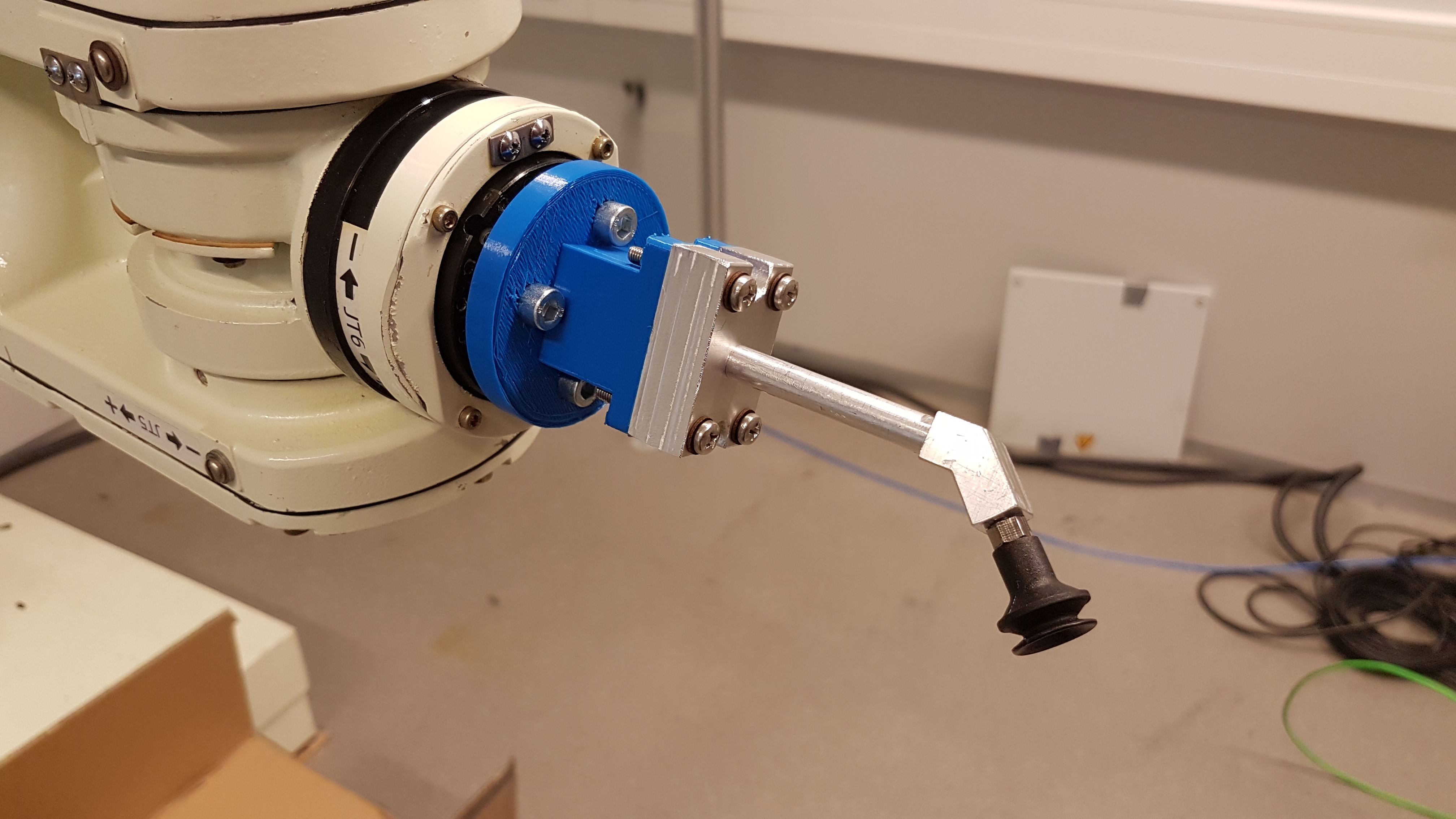
Image 4: End Of Arm Tool
The positional offset of the end of arm tool is calculated and stored to make the guidance of the robot easier.
Drop-off
A slope is built and placed for the drop-off and storage of the picked cylindrical pvc straight joints. The bottom of the slope can be used as a static pickup position for robots further in the production line.
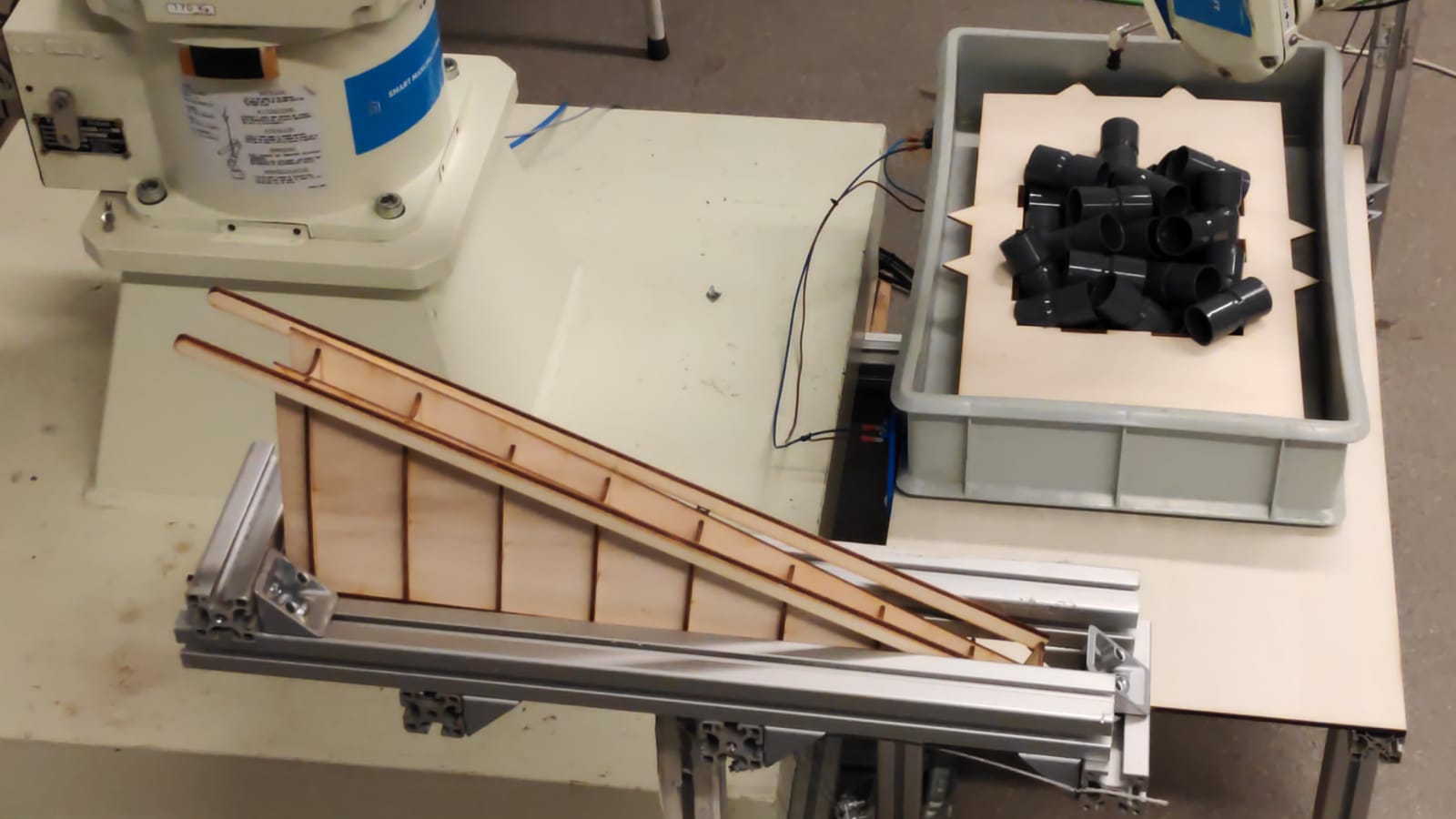
Image 5: Drop-off slope
PLC and connection
HMI
The HMI is build with a basic layout to make the use of it as simple as possible. The user has the options to load in the bin and give in its measurements and to simply start and to stop the program. When the “load box” button is pressed, a reminder to turn of the robot is displayed for safety reasons. The HMI also functions as an display for error messages for a faulty connection or a misplaced bin.
The PLC is connected to two HMIs because of the large working area of the robot, so the robot can be controlled from multiple sides of the working area providing multiple angles of view to be utilized.
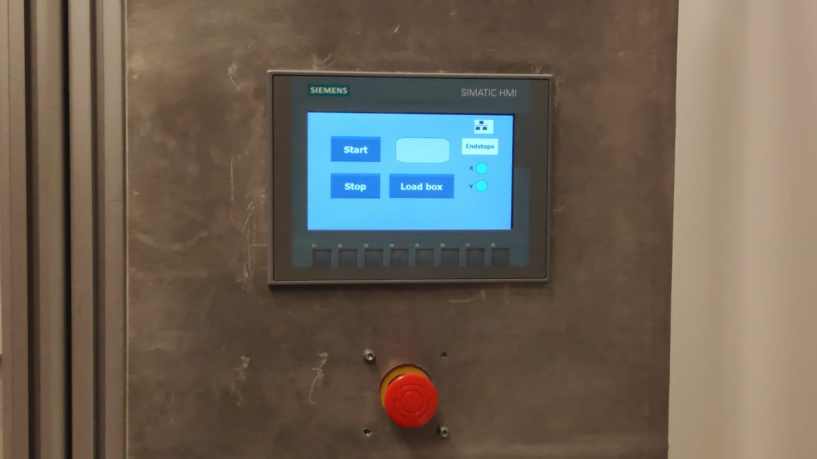
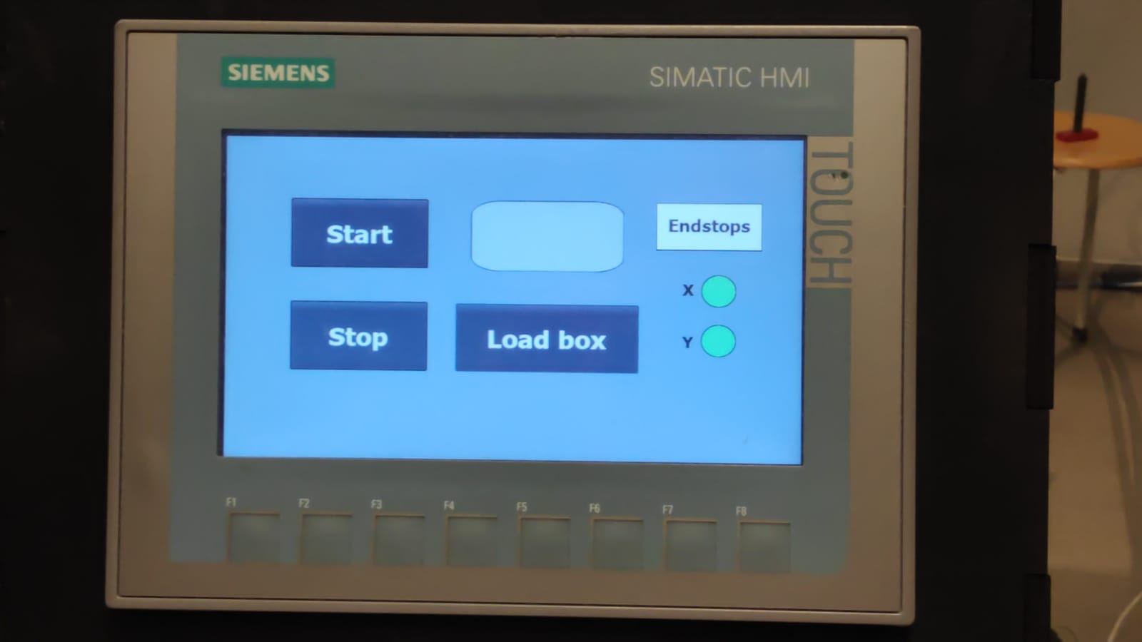
Image 6: HMI 1 Image 7: HMI 2
PLC
The PLC is used to connect the vacuum sensor, collision sensor and the sensors to check if the bin is placed correctly to Halcon and indirectly to the robot. The PLC is also a necessity for the enablement of the HMIs and their connection to the main program and the robot.