Students: Rasmus Roovers, Maup Heijke, Geran Stortelers, Jeroen Osse & Robin Lotgering
The Problem at hand
Background
The government of the Netherlands wants to minimize the noise from the railway tracks. This has everything to do with the changing regulations in noise disturbance in urban areas and the demand of new houses. Volkerrail is one of the subcontractors of repairing and extending the Dutch railway network. They got the assignment to place sound dampers on certain railway tracks. They also believe that the number of tracks that need to be silenced will grow in the future.
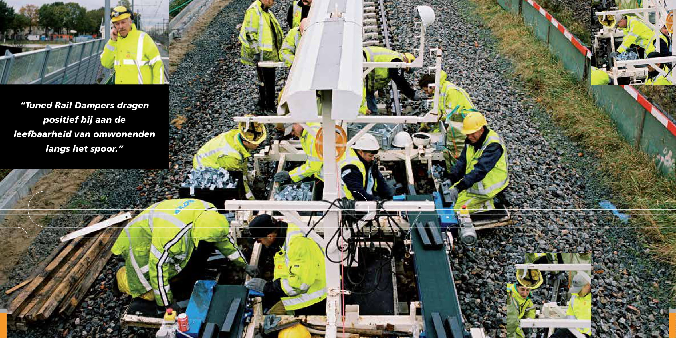
Figure 1: A page from the brochure “Raildempers” of VolkerRail in which is displayed how the dampers are placed on the rails by hand. The cart in this picture was only used when they could work longer then 6 consecutive hours.
Procedure
Until now VolkerRail placed dampers on the rails by hand (see figure 1). A group of 12 to 16 men is needed to place the dampers on both sides of both rails. At first the stones underneath the rails are shoved aside to create space around the rails. Then a cart with paste spray drives over the rails and sprays a paste at the designated locations. A cart with pallets stacked with dampers is driving behind. From this pallet the dampers are picked and thrown on the side of the rails so the workers behind that cart can place them on the paste. Finally, clamps are attached on the dampers and get a hit with a sledgehammer.
The Problem
The workers do the depalletising, transport between pallet and position on the rails, and placement of the dampers by hand at a relatively high speed considering those dampers are 0.3m long and weigh around 6 kilos. In the middle of the night these workers work effectively 3 hours in which they cover up to about 400 metres of rails. They also place the dampers on the rails by hand and therefore have to work on their knees in uncomfortable positions.
The weight of the sound absorbers and the amount that needs to be placed on the rails is physically exhausting and damaging the workers. We were asked by VolkerRail to come up with a proof-of-concept in which the workers get relieved from this physical intensive work.
The Solution
The Damper Positioning System (DPS) takes over all physical actions which involve the sound dampers. The DPS is divided into 3 parts that work together: the depalletiser, transportation and the placement mechanism.
Depalletiser
Two key parts of the assignment were moving the dampers from the pallet onto a transportation mechanism and reorienting the dampers so they could be placed correctly onto the rails. In this system the two parts are combined. The input is the pallets being placed on a cart with a forklift. The output should be the dampers placed on a conveyor belt in the correct orientation.
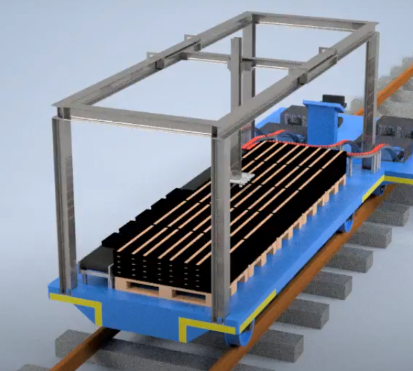
Figure 2: CAD-model of the scaled-up version of the DPS.
A TTT-robot (also Gantry-crane) was chosen to fulfil the task of depalletising (see figure 2). This type of robot has the benefit that it operates above its field of operation. It can also be integrated in the structure of the cart on which the pallets are stacked. In the proof-of-concept this robot is replaced by a six-axis UR-robot programmed with movements like it functions as a TTT-robot (see video). The robot gets information from an IR-camera that measures the distance from an object to the camera. This way the X-, Y- and Z-coordinates can be determined.
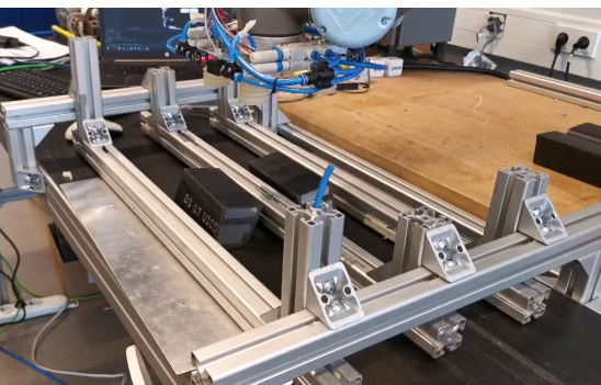
Figure 3: The three beam construction which are used to rotate the dampers in the correct orientation
Above the conveyor belt is a construction of three beams. After the robot picks the dampers, it drops them on the set location of the beams as shown in figure 3. This way the dampers turn 90° and are in the correct orientation to be placed on the rails.
Transportation
Alongside the pallets inside the roofed cart is a conveyor belt. At the end of this conveyor belt a divider guides the dampers onto separate roller conveyors (see figure 4). These conveyors lead to the placement mechanism, where the damper will slide into a temporary holding tray. In the scaled-up version of the DPS a professional roller conveyor needs to be designed to bridge the gap between the two different carts.
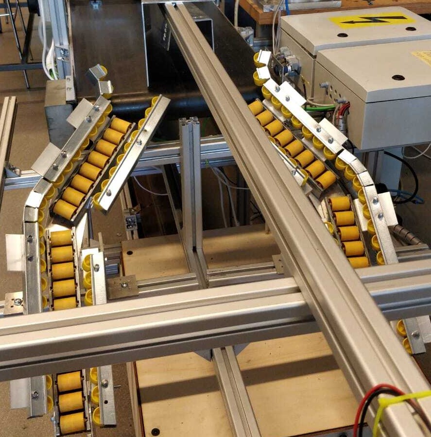
Figure 4: The roller conveyors in the proof-of-concept
Placement Mechanism
The big challenge of creating a placement mechanism is solved with a four-link mechanism moved by two pneumatic cylinders, a small and a big cylinder. The big cylinder is positioned so that the arms make a swing downwards in a circular movement towards the side of the rails. The small cylinder is installed in a way that it can affect the end of the arms with a small near-linear movement. Figure 5 shows the mechanism in ‘up’-position. When the small cylinder extends the end of the arms moves downwards to pick-up the dampers. After this move the tray drops. Now the mechanism can move to the ‘down’-position shown in figure 6. The damper is close to the rail but is not yet push into the correct spot. When the small cylinder extends it moves sideways to push the damper against the rails.
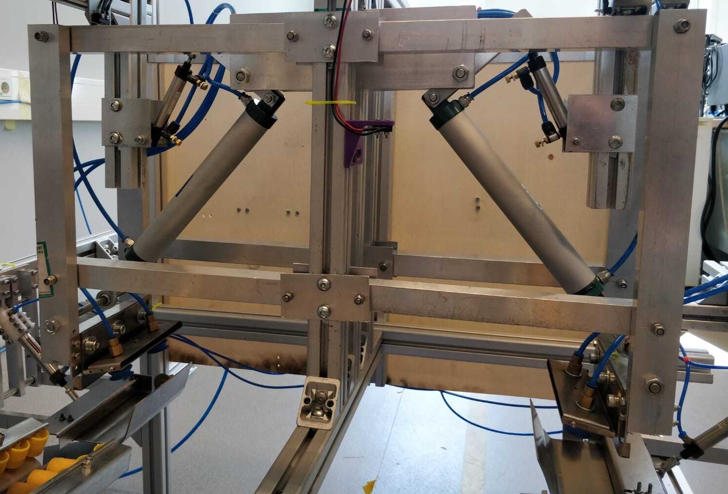
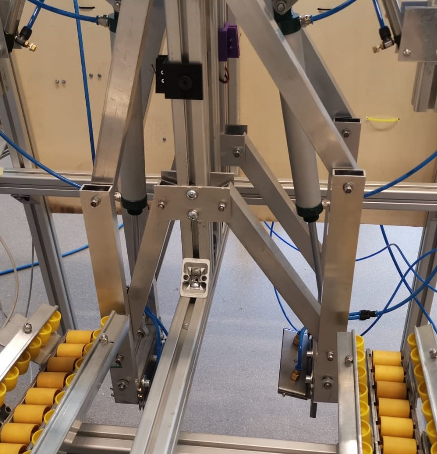
Figure 5: Four-link mechanism in ‘up’-position Figure 6: Four-link mechanism in ‘down’-position
Close to the placement mechanism is a camera that detects the vague white spots of paste. It will give a signal when a spot passes the camera. Because of the set distance between the camera and the placement mechanism the timing can be very accurate to initiate the placement of a damper.
Conclusion
The proof-of-concept set-up was not very consistent. Especially the placement mechanism was faulty because of the limited resources in the lab. Nevertheless, we accomplished to show how the principle of the DPS could work. It was a matter of fine-tuning and time to make the whole system work.
We would like to thank Mr. Van Buuren, Mr. Visser and Mr. Nijhuis from VolkerRail for their friendly and clear communication with us. Our gratitude also goes out to Thijs Brilleman and Mathijs van der Vegt for the general coaching and tech support. At last, special thanks to Lloyd Post for clearing up some PLC issues and to the workshop managers at THUAS for letting us make the parts for our proof-of-concept.