Students: Ian de Boom, Matthijs Kenis, Zeynel Koca (2021)
AV Flexologic
AV Flexologic is a company which produces and sells various machines for the flexographic printing industry. These machines print the labels of various products, almost all product labels have been made using a flexographic printer. Flexologic sells their machines to companies which want to print their own labels.
Flexographic printing uses a flexible printing sheet, this sheet is pressed around a sleeve (a cylinder with the exact diameter to be able to print the full print sheet). The print sheet gets covered in ink and the sleeve is pressed against the product and rotates so the full print is left on the product.
See image 1 here below:
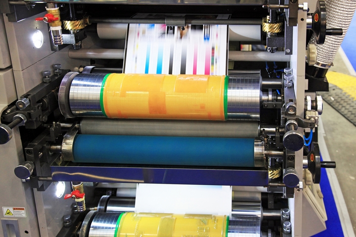
Image 1: Flexographic printing (https://silverme.net/en/gallery/)
Because the sleeves has to be the exact same diameter as the length of the printing sheet, its very important that the right sleeve is being used in the right machine. Which brings us to the assignment given by Flexologic.
The assignment
The current situation at Flexologic is that the sleeves enter the specified machine by hand, sometimes by multiple people depending on the weight of the sleeve. Flexologic is trying to replace this human process by automating it with a robotic arm.
In this situation, a sleeve-rack is placed with all the sleeves necessary to fulfill the current job. The robot arm then picks the sleeves individually and places it in the right machine. See image 2, here below:
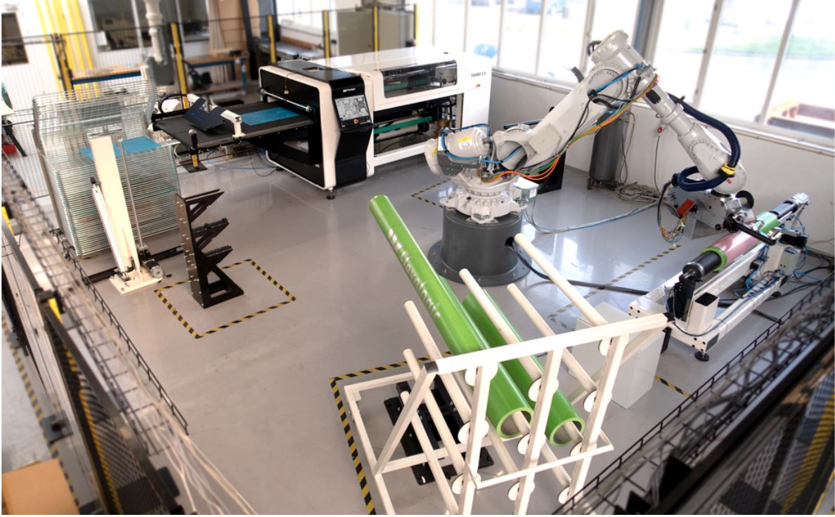
Image 2: Robot arm and sleeve rack (https://www.flexologic.nl/products/robocell/)
This situations still leaves the door open for some errors, mainly human errors. The robot is programmed to pick up a sleeve from the sleeve-rack, but if the operator places the wrong sleeve on the rack, the robot would damage the sleeve, or use the wrong sleeve.
For that reason Flexologic has given us the assignment of replicating their situation and applying machine vision to detect the sleeves on the rack and determine if any of the sleeves are wrong. Apart from that, the machine vision camera will also need to be able to determine the orientation of the sleeve placed on the rack. This way the robot can adjust itself if the sleeve is placed on an angle and by doing so preventing any further damage to the respective sleeve.
The execution
There are three important dimensions for the sleeve detection, the outer diameter, the length and the orientation. All of these are measured by a depth camera (Intel RealSense D435), using the robot, this camera is placed right in front of a sleeve and detects these three dimensions, per sleeve.
The robot
To be able to detect all the necessary dimensions for every sleeve, the camera needs to be placed right in front of each sleeve. Therefore the robot needs to move along a predetermined path so all sleeves will be visible for the camera.
This path starts with a global view, getting all sleeves in frame so the camera can detect if the sleeve-rack is filled with sleeves or not. After this, the camera will go in front of each individual sleeve that was detected to measure the dimensions, See the gif here below. If the camera detects the right sleeve length and diameter (which is chosen at the start of the job) it will pick up this sleeve and place it elsewhere.
Gif 1: The predetermined path of the robot
The gripper
The robot is able to pick up the sleeves, because of the gripper, see image 3 below. On the underside of the gripper there is an FESTO Clamping Module placed, this clamping module expands under pressure. The gripper goes into the sleeve with the corresponding diameter, the tolerances of this fit are around 5 mm. When the gripper is placed in the sleeve, the clamping module expands by 5 mm and is stuck in the inner diameter of the sleeve, this way the robot can pick up and move the sleeve.
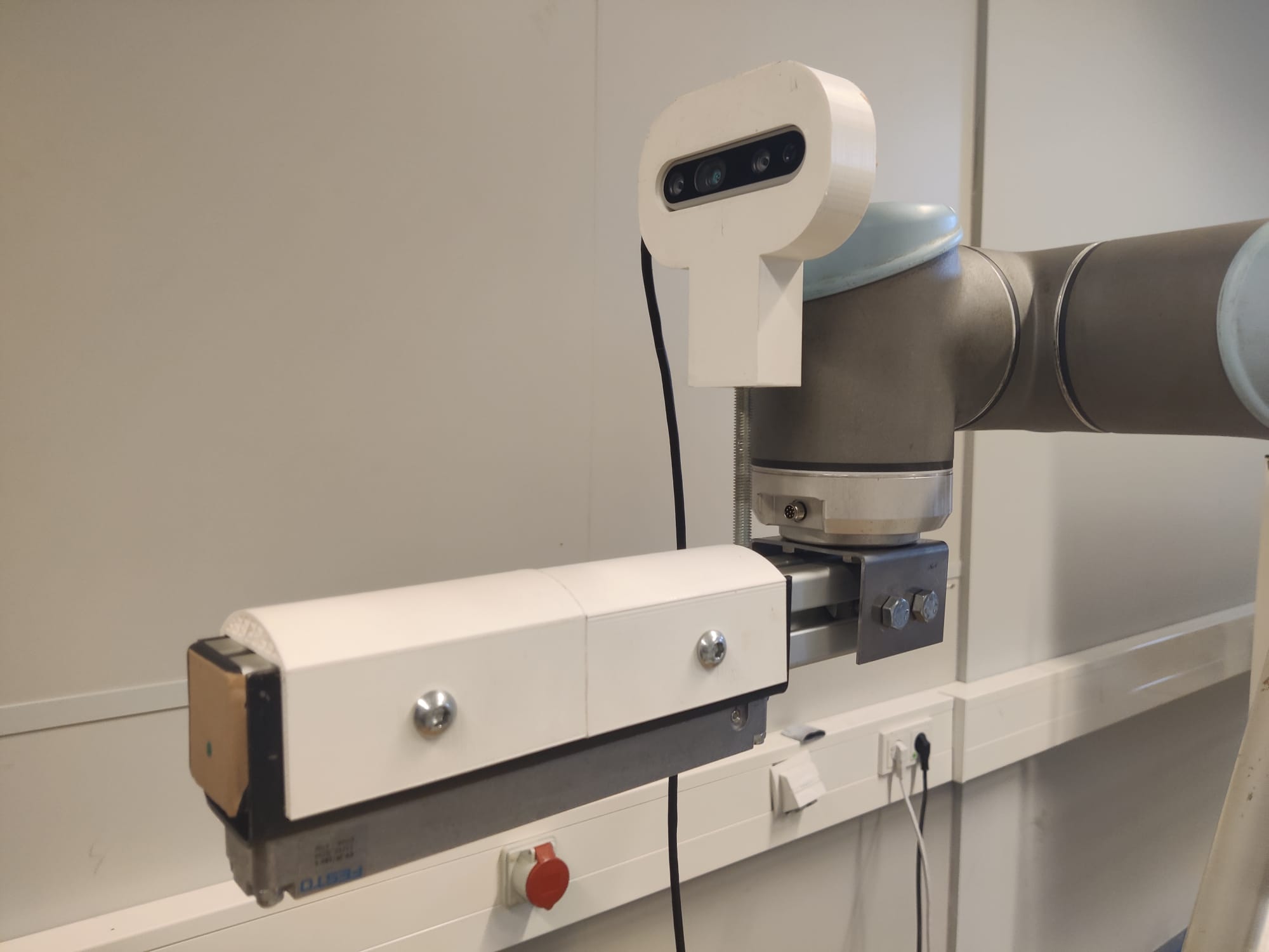
Image 3: The gripper
Diameter detection
The outer diameter is measured by taking the most outer pixel-points of the detected circle of the sleeve. By converting these pixel points to world coordinates, we can calculate the distance between these coordinates and thereby determine the diameter. See image 4 below:
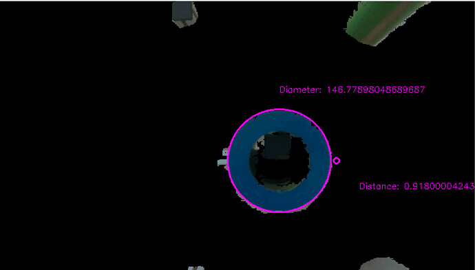
Image 4: Diameter detection
length
The length is measured by making the camera pick up a point on the sleeve which is the closest to the camera. Because the distance of the sleeve-rack to the camera (by using a pre-programmed static point) is always the same, the difference between the sleeve-rack and the point closest to the camera, is the sleeve’s length.
Orientation
The orientation of the sleeve has to be determined in order to move the gripper into the sleeve without colliding with the inner wall of the sleeve. With the use of OpenCV the contours of a selected sleeve are detected. A line is drawn through the middle of these contours representing the longitudinal axis of the shape. See image 5 below. With the pixel- and depth information from two pixels on this line a vector can be calculated which represents the direction of the longitudinal axis of the sleeve in the coordinate system of the camera. Assuming the gripper is correctly aligned with the Z-axis of the camera, the angle between the gripper and the sleeve can be calculated and subsequently corrected by the robot. By repeating this calculation a number of times and selecting the mean value from this list the accuracy is improved.
With the sleeve and the gripper pointing in the same direction, only the middle of the sleeve’s diameter has to be located. This is done by locating the minimal and maximal values of X and Y from the detected circle and finding the translation needed for the robot to move the gripper to the middle of these four points. The gripper is now in the correct location to be moved inside the sleeve.
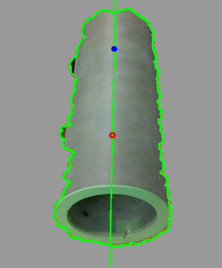
Image 5: Contour line