Students: Ishvara Lalta | Talha Erbilli | Stefan van der Lee | Rick van den Eng
Fokker Aerostructures is a subsidiary GKN Aerospace and is specialised in the design, development and production of lightweight constructions. They develop modules and landing gear for the aviation and defence industry.
The “Challenge”
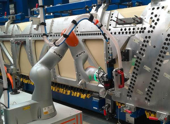
Fokker has a production line that is part of the manufacturing process of the airplane flap for the Airbus A350 airplane. Here, Fokker drills holes in carefully calculated locations with a very precise tolerance. To maintain the precision of the sizes and the location of the holes Fokker uses a massive aluminium mold which is placed over the airplane flap (fig.1).
To drill some of the holes, Fokker currently uses a Kuka LBR iiwa 7 R800 in combination with a teaching method to insert the special pneumatic drill that is attached to the robot as an end of arm tool. Some of the holes are not to be drilled, these holes have a temporary fastener attached to them with a green color on the surface.
The problem with this method is that it’s fairly time-consuming as each hole has to be manually taught to the robot. On top of that it’s also not flexible at all because a change in the position of the target or the robot-arm itself requires a complete reteaching of the positions of the holes.
Fokker wants a solution in which the holes are detected automatically using a vision-based system and in which hole insertion and drilling is also automated. This would make the system much more flexible, dynamic and therefore future-proof. The solution for this problem will be developed using a UR-10 robot.
The mold
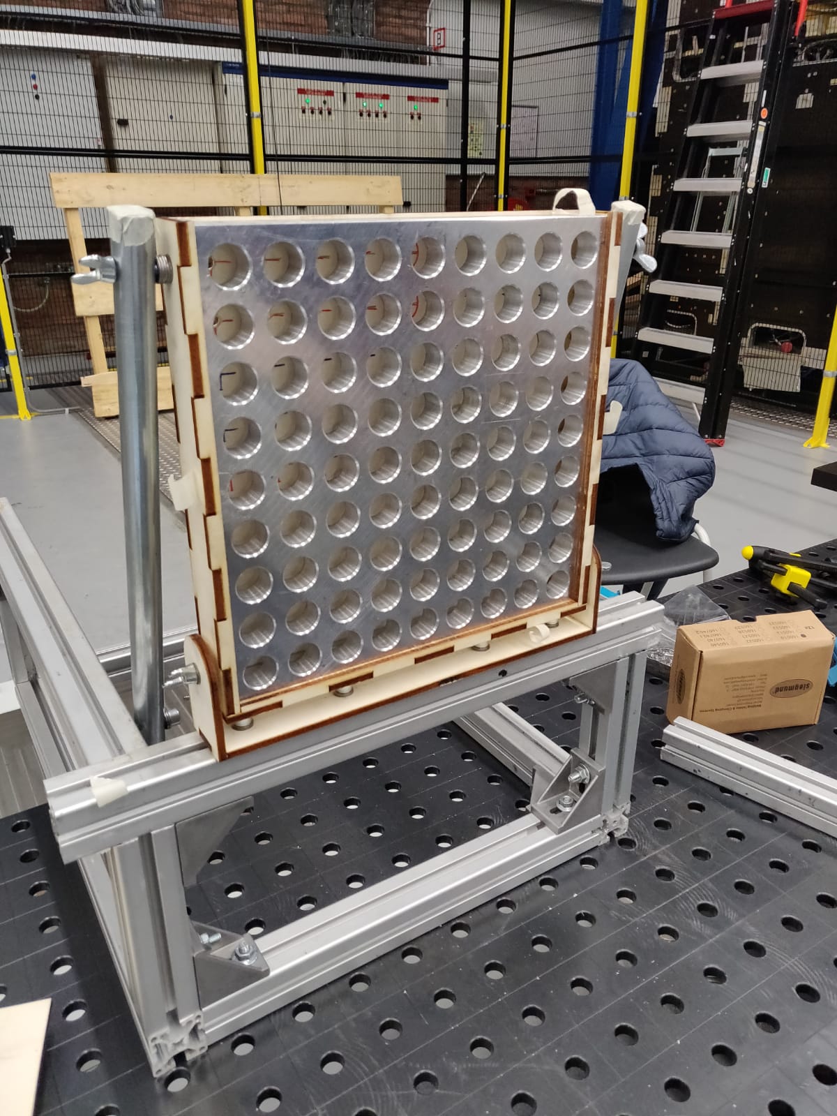
The mold that Fokker is currently using is as big as the actual airplane flap, several meters across and up. The mold is made of a special type of massive aluminum so that the holes retain all of their properties of a very long period of time. Since the actual mold is sizable and expensive, Fokker made one of their testing molds available for this project. The size of the testing mold is 30 x 30 cm and it contains 81 holes of 25mm tapered off to 23mm in diameter (fig.2).
The drill
Currently fokker is using a pneumatic drill as the end-of-arm-tool of the robot. The drill is a special type of drill of which the head expands once it is inserted in a hole. After the head expands and the drill-head locks itself into place by putting pressure on the entire inner surface of the hole, a smaller diameter drill comes out and drills the actual hole in the flap. This system makes sure that the holes are drilled exactly where they should be.
The tool that is used in this process has a large body which often gets in the way when the robot needs to avoid obstacles.
The drill-head of the tool has a diameter of 22.9mm, meaning that during insertion of the drill-head into a hole the tolerance is just of 0.1mm.
The actual drilling tool is currently in production service at the manufacturing hall so Fokker could not make it available for this project.
An aluminium cylinder with the same dimensions as the drill-head had to be manufactured. Because the project is concerned with the insertion and not the drilling this solution worked perfectly fine. Smaller diameter cylinders also have been manufactured to test the relevant tolerances.
Vision
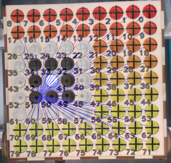
The vision system is used to detect the holes, obstacles, color and it also gives an approximate distance from the end-of-arm tool to the surface of the mold. The camera that is used to gather this data is the “Intel realsense SR300”. The opencv library in python is used to detect both the holes and the obstacles (temporary fasteners). The holes around the temporary fasteners are also exempt from drilling because of the size of the drill.
Human Machine Interface
To operate the robot smoothly, a HMI (Human Machine interface) has been made.
The system operator can control various processes and the emergency button of the system.
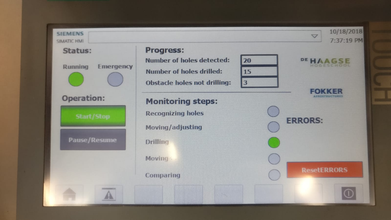
The HMI can:
– Start and Stop the process
– Pause and Resume the process
– See the progression of the process
– Display errors
End of Arm Tool
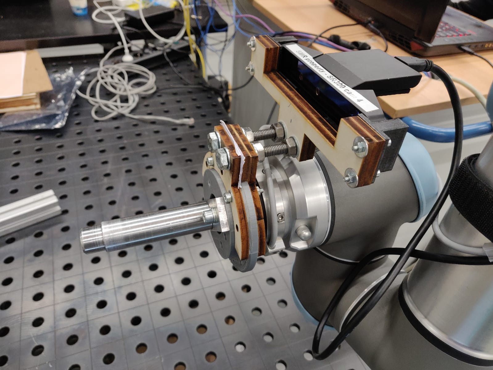
The end-of-arm tool that has been developed to simulate the drill-head consists of a Machined aluminium cylinder, a laser-cut wooden backplate and finally a 3D-printed camera holder for a Intel realsense SR300. Other than the selfmade parts, the end-of-arm tool consists of the camera and a OPTO-axis Torque sensor or “optoforce sensor”.
Solution
The final solution that came together is a combination of machine vision, high precision sensors and mechanical design. From start to finish, each hole takes approximately 50 seconds to drill. This accounts for the distance measurement, hole detection and insertion sequences.
The biggest challenge the project faced was the small tolerance of 0.1mm, this small tolerance made it difficult to insert the drill-bit into the holes because of the lack of precision that is achievable with just vision.
The implementation of the Optoforce sensor is one of the biggest assets to the final solution of this project. The optoforce sensor gives room for small imperfections in the vision system. This helps a great deal with the flexibility and robustness of the robot as a system. Using this smart solution, the difficulty of having to approach a very small tolerance using vision is relatively easily solved by the optoforce sensor.
The result of the implementations of this solution is a robust system that can detect holes and maneuver to simulate the drilling process all the while looking for obstacles and avoiding them.