Students: K.A.A. Kohabir, M.L. Liendo, S.A. van Pomeren, J.A.A. Verstraeten
The project description
For the assembly of certain parts, Radial-Lok fasteners are used by GKN Fokker. A disadvantage of this type of fastener is the remaining stem, as shown in Figure 1. The stems are currently removed manually with a shaver head grinder. Fokker’s need is to automate this process as efficiently as possible.
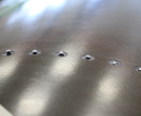
Figure 1: Radial-Lok stem
The goal
The goal is to automate the Radial-Lok shaving process. To accomplish this a universal robot is used in combination with a force-torque sensor to measure force and a Linescanner to measure Radial-Lok height as quality control.
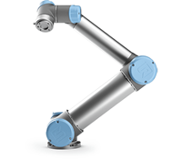
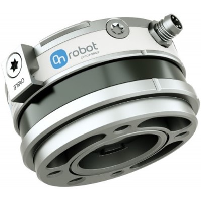
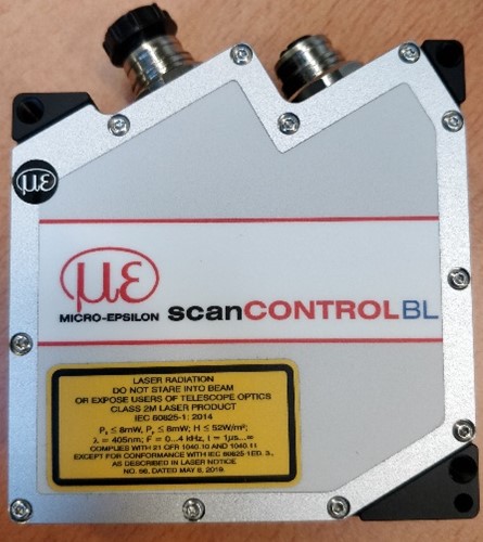
Figure 2: Universal robot Figure 3: Force torque sensor Figure 3: Linescanner
PBS
At the start of the project, a PBS was created to give us an overview of each part of the project that needs to be completed. This overview acts as a guideline for us during the completion of the project.
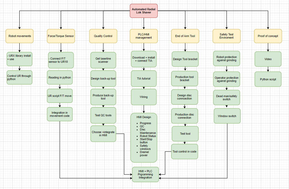
Figure 4: PBS
Challenges
During the project we encountered a few challenges. For instance, we had to attach the grinding disc in the Dremel. We had to design a special tool to do this. For the Dremel we designed a special mount that allows it to be attached to the robot’s Force torque sensor.
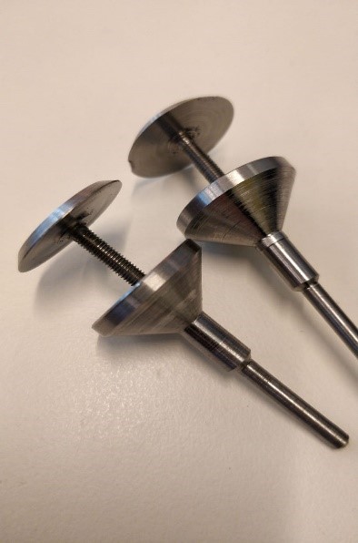
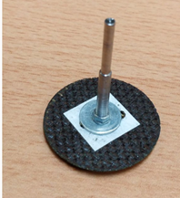
Figure 5 & 6: Dremel to Grinding disk attachment
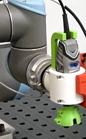
Figure 7: Dremel to force torque sensor attachment
Another challenge we encountered was the design of a cone that can be attached to the Dremel. The function of this cone is to glide over the surface of the material without damaging it. The problem was that the Dremel had to be at 6 degrees to shave the Radial-Lok correctly. To solve this we designed a cone with a 6 degree inclined bottom plane so that the cone is perfectly horizontal on the surface when shaving.
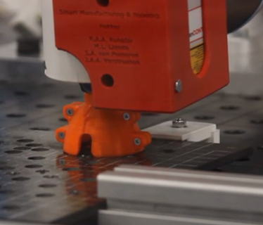
Figure 8: Dremel cone
Another challenge we encountered was the communication between python and the Force torque sensor. Since there was no proper documentation available on the internet for this sensor, it was difficult for us to get it to work. We solved this communication problem by trying different out of the box ideas until we got it working. At the end we created a code that uses the raw data send from the sensor and so we were able to incorporate it into our Python script.
Another challenge we encountered was, finding a quality control tool that was accurate enough to be able to detect shaved Radial-Lok with a maximum height of 0.2 mm. As a group we started to design our own quality control tool. We tried to design a mechanical tool that can detect the shaved Radial-Lok when the height is more than 0.2 mm. The challenge was to get the tool accurate enough to be usable for the quality control. In the last two weeks we got the opportunity to use a laser linescanner. When we got the Linescanner we invested a lot of time to understand how it works. We discovered that the Linescanner is accurate enough to be used as a quality control tool for our process. We decided to use the line scanner instead of the mechanical tool because of the level of precision we can reach. We designed a special mount to attach it to the force torque sensor so we can get accurate measurements.
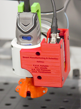
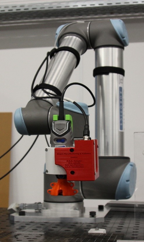
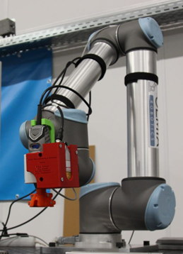
Figure 9: Linescanner attachment
Another challenge we encountered was how to integrate our Python script with the PLC program. We wanted to add the ability to start, stop and resume the Radial-Lok shaving program by pressing a button on the HMI. Furthermore we implemented a safeguard where the program can’t be started unless the safety switches are all depressed.
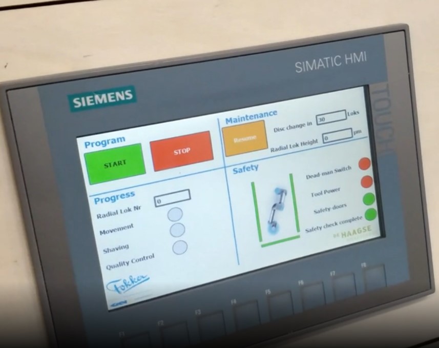
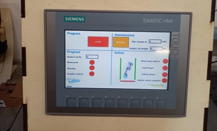
Figure 10: PLC HMI
Two important features were implemented: A pop up notice warning the operator to change the shaving disc after 30 cycles as seen in figure 11.
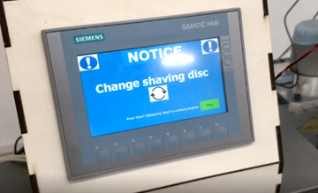
Figure 11: Disc change notification
The second feature is a pop up warning after two unsuccessful quality control attempts whereafter the robot will move to a preprogrammed position to facilitate the manual shaving of the Radial-Lok by the operator.
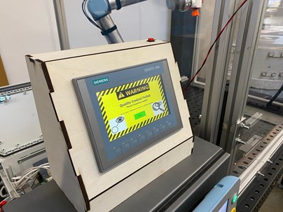
Figure 12: Quality control warning
Conclusion
At the end of this project we can conclude that after many invested hours we have managed to come up with a solution that meets all the requirements for the project. At this point we can detect, shave, and measure the Radial-Lok to the specified tolerances.
We are still limited in shaving speed due to the actual tool not being available. The tool we are using on the robot is not as robust as the one used in the original process at Fokker and can’t be controlled as precisely.
While working on this project our preference fell on using python instead of UR script since it is a more user-friendly programming language and integrates well with the other programs used.
Ultimately it was an educational period for all group members. We learned a lot while solving all the challenges we encountered during this project. We also learned a lot about how to program and debug a robot and a PLC. These skills could be utilized in future projects.