Students: Melissa Damstra, Rutger Peeters, Jonathan van de Reep, Frank Reszka (2019).
![]()

Introduction
GKN Fokker is a tier 1 aerospace supplier situated in the Netherlands. The sites in Papendrecht and Hoogeveen produce various components; such as door and skin panels for production of various aeroplanes including the Airbus A380, the Gulfstream G650 private jet and the Joint Strike Fighter, amongst others. Nowadays skin panels for aircraft largely exist of layered materials in order to achieve the stringent weight requirements. One of the biggest processes at the Fokker sites is the lay-up of these panels for metal-bonded, fiber metal laminate and composites structures.
Assignment
One of the big challenges for GKN Fokker is to automate lay-up of metal bonded fuselage panels. Aeroplane components tend to have curvature in two directions, resulting in double or saddle curved aerodynamic surfaces. Lay-up of these geometries is currently achieved by hand; this is very labour intensive and ergonomically unfavourable. Any human error in terms of lay-up or handling will result in a non-conformity or scrap part. Further, the cost of the adhesive film is a big component in overall unit cost. Different forms of adhesives, such as one in sprayable form is not feasible due to the requirement of recertification and its induced costs on already running programs. A typical production run for civil aircraft is on average 30 years.
GKN Fokker would prefer a robotic system which is able to pick and place the adhesive film sheets onto the aluminum skin. The manpower could then be used elsewhere and the material waste can be reduced as shown in Figure 1.
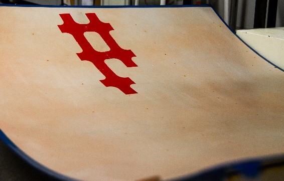
Figure 1: Automated lay-up of sheets.
The robotic prototype system (to be built and tested by the SMR1 students in Delft) must require:
- The use of a Programmable Logic Computer (PLC), machine vision camera subsystem and a Universal or Kawasaki robot;
- The use of replaceable adhesive sheets (dimensions 150 by 100 mm);
- A working End Of Arm Tool (EOAT) to pick the adhesive sheets from a 2D surface (cutting table) and placing it in the curved mold (3D).
- A maximum cycle time of 20 seconds per sheet.
- A placing tolerance of 1±1 mm between the edges of the adhesive film (no overlap).
The ALOMBA solution
ALOMBA is an abbreviation of the essence of the project: Automated Lay-up Of Metal Bonding Adhesive. The ALOMBA team created a robotic prototype system to pick and place sheets from a 2D to 3D surface within the time frame of 5 weeks.
The setup of our solution consists of four subsystems:
- End Of Arm Tool;
- Quality check, and;
- Robot programming and control;
- Floor plan.
1. End Of Arm Tool
This tool (placed on the end of the Kawasaki robot arm) is the mechanical challenge of the project. Currently, there is no off the shelf tool in existence which can fully handle the 2D pick and 3D placement of adhesive sheets. The design of the EOAT is composed of a robot mounting system, damping system, grid picking system and an air duct, see Figure 2.
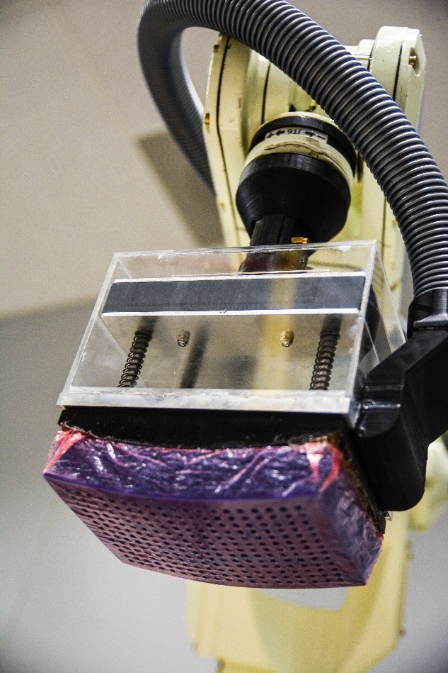
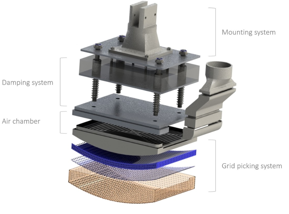
Figure 2: The End Of Arm Tool with its various subsystems.
1.1 Design
The end effector tool is designed to pick sheets from a cutting table and placing them on the double curved mold, without leaving pockets of air between the sheet and the thin aluminum skin panel. Like previously mentioned, the transition of 2D picking to 3D placing requires a form of compliance; the elastic deformation of a material to enable form changes when a force is applied. Foam in the form of a sponge is a great material to use in this application. It provides shock absorption when a sheet is placed and it will deform to follow the curves of the mold. However, to maintain high placing accuracy, the form change of the sponge on the EOAT should not be too drastic. In addition, the sponge’s consistency could also change over time. If this would be the case, the tolerance between consecutive sheets will not be within the required range.
Secondly, an extra damping system is introduced using linear bearings, see Figure 3. This mechanism provides an extra built-in machine safety. The multiple damping systems will not act as an overabundance of damping, because they are used for different purposes. The linear bearings in combination with springs will act as a buffer, so the EOAT will not damage the fuselage skin panel when the Kawasaki firmware malfunctions.
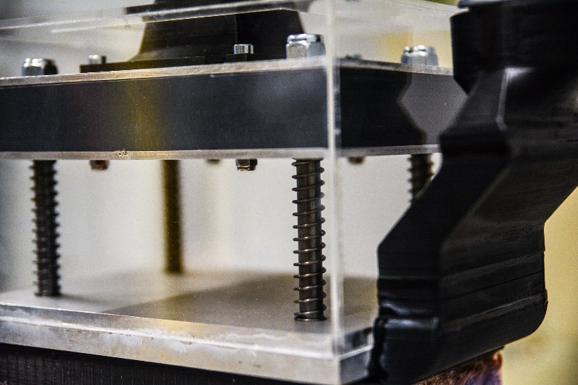
Figure 3: The spring and linear bearing damping subsystem.
The sponge takes the shape of the 3D mold due to pressure on the EOAT, resulting in the sheet adhering to the aluminum surface. Lastly, the pressure exerted by the Kawasaki arm on the mold can be regulated in a way that it will not locally cure the adhesive sheets, which a heating element would do. This would otherwise be unfavourable, because this happens later in the autoclave process.
1.2 Flow generation
In order to generate enough flow to lift up the sheets, a vacuum cleaner was chosen. Figure 4 showcases the connector from the vacuum hose to the air chamber.
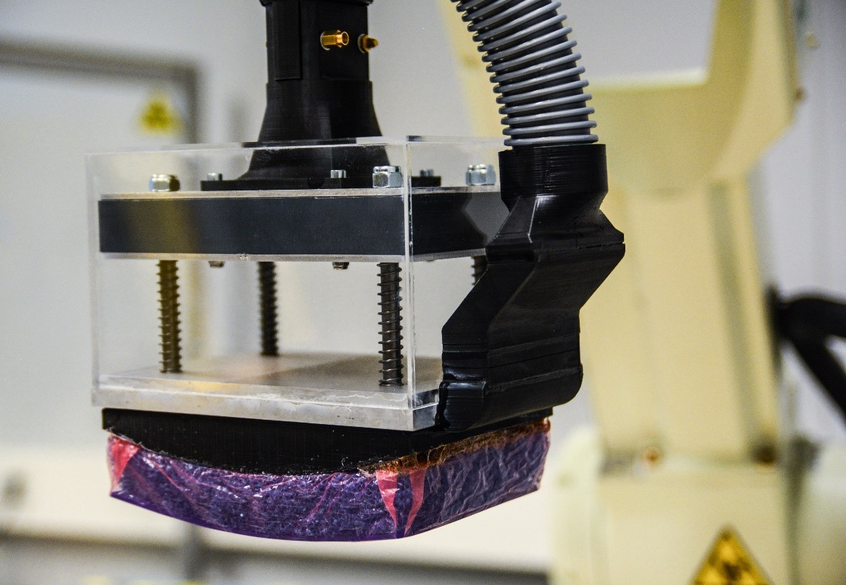
Figure 4: The connection from air chamber to vacuum hose (positioned on the right side).
2. Quality check
A vision system is integrated into the entire robotic system to check whether the adhesive sheets are picked up correctly, see Figure 5. This is done by moving the Kawasaki arm over a box with a camera. The camera detects whether a sheet is picked up and if it is located at an angle relative to the centreline of the EOAT. Due to the integration of the vision system, the Kawasaki arm can automatically correct the deviated angle. This adjustment assures the correct placement of the sheets.
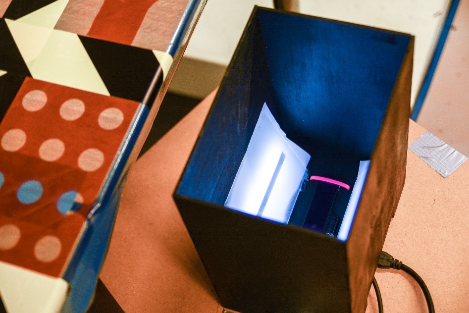
Figure 5: Black camera box next to the cutting table.
3. Robot programming and control
The various required systems (PLC, machine vision and EOAT) have all been integrated to cooperate as the robot completes its cycle. The Programmable Logic Computer (PLC) and the Siemens HMI display form the graphical user interface for operating the robotic arm outside of its enclosure, see Figure 6. The Kawasaki program communicates with the machine vision software each time the arm approaches the vision box. As the robot continues its cycles, it will automate the lay-up of the adhesive sheets.
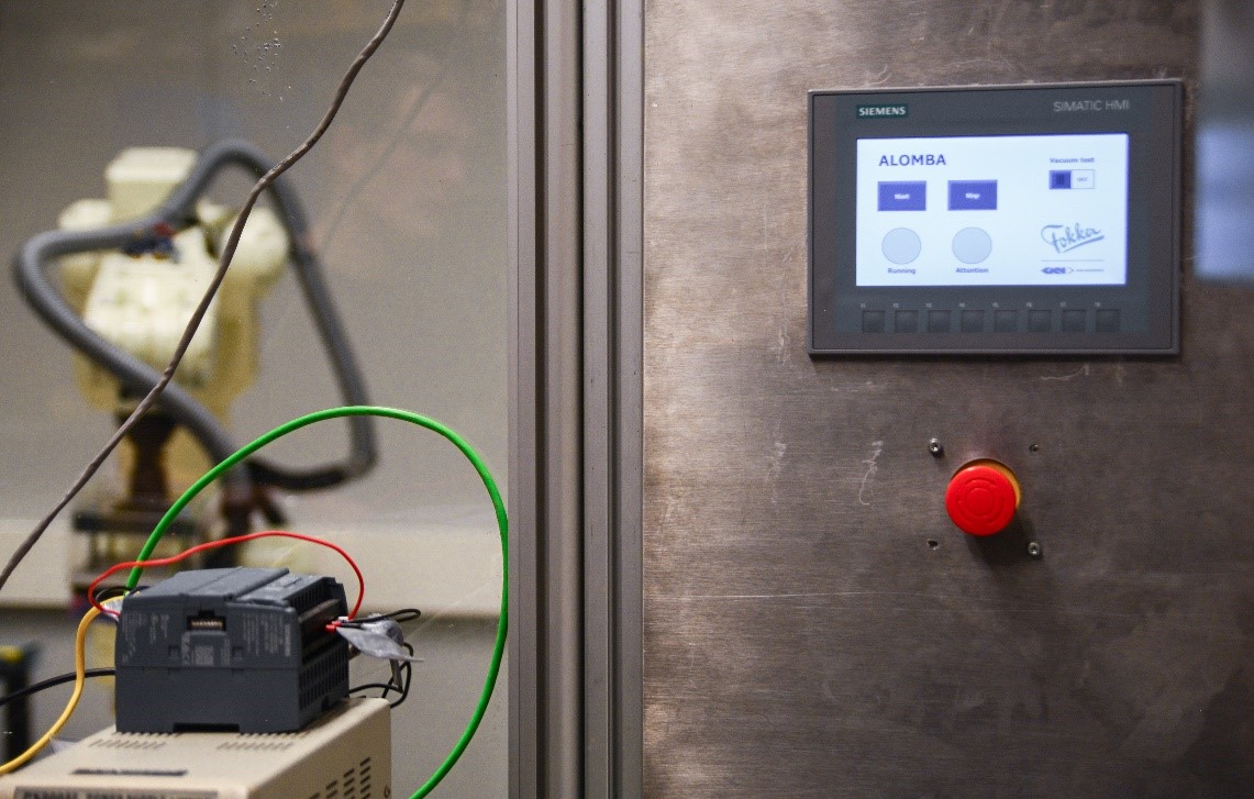
Figure 6: The PLC (left) and HMI display (right).
4. Floor plan
Figure 7 shows the floor plan used in the SMR workspace. This setup is specifically designed to fit the smallest possible space. This is important to achieve the shortest cycle time. This will be an important aspect to keep in mind when GKN Fokker eventually scales up and industrializes the entire lay-up system. Less robot movement generally means less time wasted.
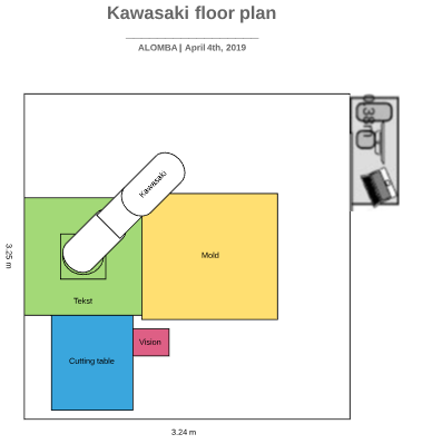
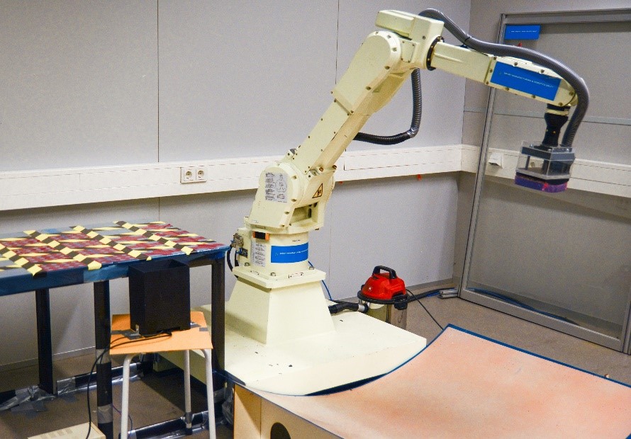
Figure 7: The floor plan (left) and real-life setup (right).