Students: Wendy Exterkate, Marten Haaksema, Noa Veth, Ted Vrijburg. (2022)
Introduction
GKN Aerospace is a leading global tier one supplier of airframe and engine structures, landing gear, electrical interconnection systems, transparencies, and aftermarket services. It supplies products and services to a wide range of commercial and military aircraft and engine prime contractors, and other tier one suppliers.
Current situation / Assignment
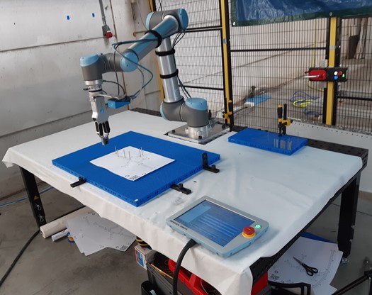
There are a lot of cables that go into an airplane. These are set up in big harnesses at GKN Aerospace and then shipped to the plane. These harnesses are laid down on a board with the help of pins and a schematic drawing.
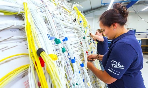
Currently the placing of those pins is done by hand, but GKN Aerospace want this to be fully automated and has asked us to make a prototype to prove the placing of the pins can be done by a robot. The (old) situation is:
First a table with a board on it is grabbed. Then, a schematic drawing with the cables is put on top of it. Someone grabs some pins and puts them in the board (through the drawing) based on their own judgement.
What GKN wants are two options. The first is that a table with a board on it is grabbed and rolled in front of the robot. Then, a drawing with the cables and pin locations on it is put on top of it. The robot reads the QR-code on the drawing, determines where to put the pins and does so subsequently.
The other option is that after the table with a board is rolled up to the robot, the operator manually selects which drawing he wants, and the robot places the pins.
Problems / Adjustments
During the making of this robot there were some difficulties we had to deal with. Making a database with coordinates and corresponding drawings wasn’t difficult. As was making a code that could get the coordinates from the database, transform them into robot coordinates, then into hole positions and these hole positions into robot coordinates once again. Getting the robot to move and the camera to take pictures was however not that easy.
moving the robot
When given the robot a move command using ‘try’ and ‘except’ the robot would only execute the first move command in the try and then immediately go to the ‘except’. The robot also wouldn’t repeatedly go to the position we asked him to go to. Sometimes he decided to go to somewhere else, though the code hadn’t changed. After researching the problems, it was discovered that the robot has an error, which we were unable to resolve. It was decided to work around the command problems by using multiple ‘try’ and ‘excepts’ with only one line of movement in the ‘try’ and that every time the robot had to do something the TCP (Tool Center Point, the orientation of the robot) would be reset.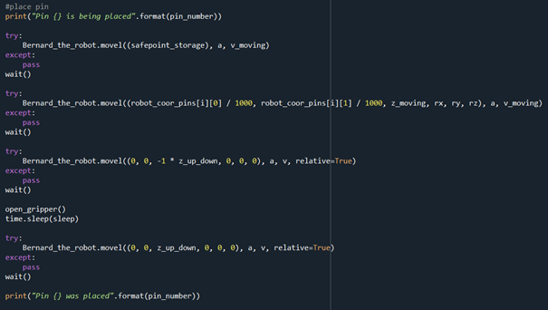
opening and closing the gripper
Getting the gripper to open and close also posed a problem, we were unable to get the gripper to react through code. It was decided to make a script in the robot and run that script through sockets. That also had some difficulties, since the robot didn’t close and clean up the socket port even though we instructed it to do so. Because of this it got overloaded and quit. After a certain amount of commands the robot has to be reset to keep the robot running.
Scanning the board
We had the idea to also determine the coordinates and angle of the board so the board could be in any position to move the pins. This worked in theory and in code, but in practice the pins often hit ridges. This was because the accuracy of the camera was too low. A difference in 1 degrees on a board with holes of 6x6mm is a lot. It was decided to have the board in a fixed position. 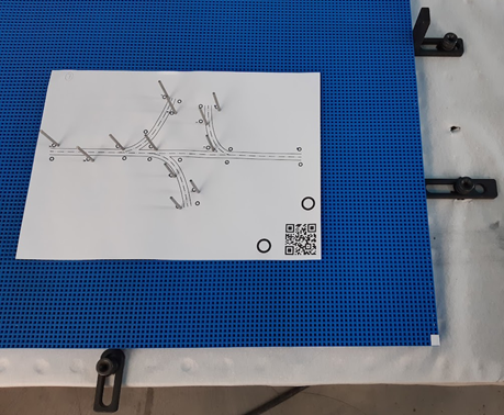
The end result
We made a website where an operator can choose to place or remove pins. For both the placing and removing there are two options, to select a drawing or to place a drawing on the board.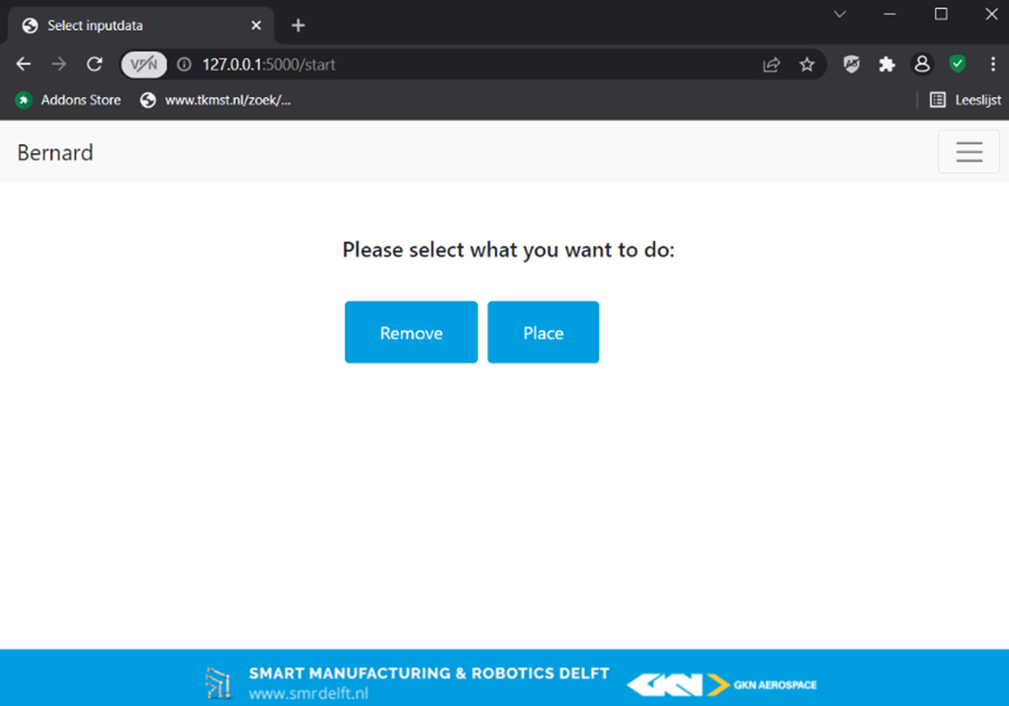
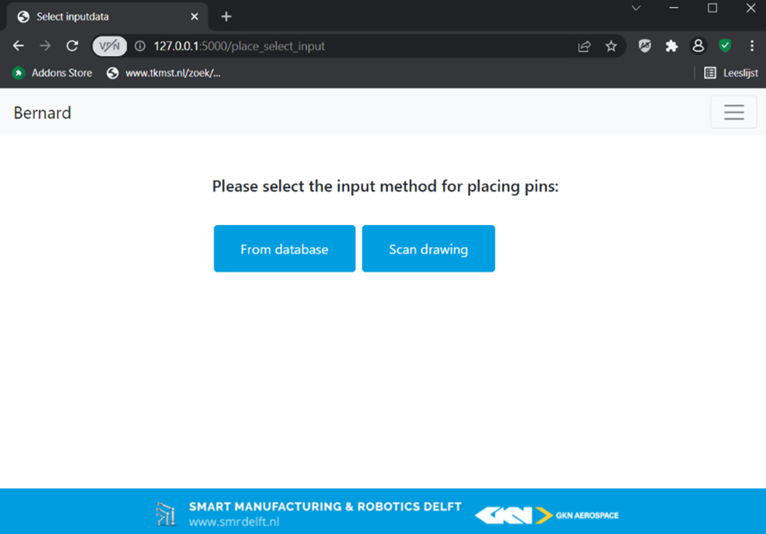 When selecting a drawing the robot will get the coordinates of the pins on the drawing from a database. These coordinates are first transformed into robot coordinates. After which the hole in the board closest to the coordinate is selected and retransformed into robot coordinates. The robot will now start placing the pins.
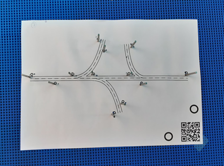
When the other option is chosen a drawing can be placed on the board, the robot scans the board and determines the coordinates and angle of the corner of the drawing and the position of the QR-code. The robot takes a close-up of the QR-code and reads the QR-code to see which drawing it is. The coordinates are gotten from the database and transformed into robot coordinates with the help of the coordinates and angle of the drawing. The hole in the board closest to the coordinate is selected and retransformed into robot coordinates. The robot will now start placing the pins.
For removing the process for the two options, to select a drawing or to recognise a drawing on the board, are the same.
Conclusion
Despite the fact that we ran into many problems we were able to make a robot that can place and remove pins, whether it is a drawing selected on the interface or a drawing that is placed on the board. We are happy to provide GKN with a robot/prototype that proves that the placing and removing of the pins can be done by a robot.
Our thanks go out to our teachers Matthijs van der Vegt and Thijs Brilleman, and our clients Rik Tonnaer, Ronald Hageman and Dominika Chamoro.
Also a special thanks to SAM|XL & GKN aerospace
![]()
![]()