Students: Laurens Gosseling, Marcel Koop, Frits Hoogendijk. (2019)
![]()
Introduction
Nowadays campers are becoming more popular every day. To clarify the types of campers, see the following figures 1 and 2.

Figure 1 – An integral camper
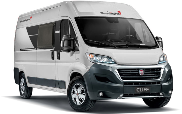
Figure 2 – A camper van
In order to supply this huge demand of campers, there are many camper builders. These custom made campers are often camper vans. The vans are simply bought from the car manufacturer. Next, these vans are transferred into a camper by cutting holes in the bodywork for the windows. Then they place the prefab windows in the vans and the builders start working on the interior.
The original situation
As written above, the vans are bought from the car/van manufacturer. From there on the van is being transferred into a camper by cutting holes for the prefab windows. The first step before cutting, is measuring where the window should be placed. After measuring the cuts, the camper builder uses nibble scissors or a jigsaw to create the cut outs in the bodywork. This simple process already takes one single day. After placing the camper windows, the carpenter creates and assembles the interior in the van: this takes another day.
The problem
HORREX would like to shorten the time of the cutting part.
Cutting the window itself only costs several minutes, but measuring the location and the shape of the cut out takes a lot of time. Another problem of measuring by hand is the location and the shape tolerance. Therefore the desired tolerances of the placing and the shape are both ± 5 mm.
For this proof of concept, HORREX would like to automate the cutting and the measuring process of a Fiat Ducato L2H2. But we have to keep in mind the scalability to other vans.
Our solution
The students think it is a great idea to put the robot on a table and put it in the loading space of the van. From this location the robot is able to cut in all surfaces around. Unfortunately this location is not a fixed position as each van is different, therefore HORREX places the robot within a tolerance of ± 5 cm. Due to this tolerance, the table can also be rotated (as shown in figure 3) and that gives us another challenge: how does the robot know where it is positioned in respect to the outer shell of the van?
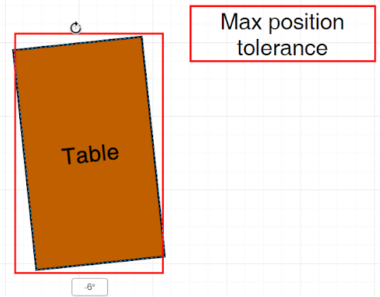
Figure 3 – Maximum tolerance shown
The students came up with the idea to use computer vision to get the rotation and the position of the walls. There is a Python library which can do exactly what the students would like to achieve, it is called ‘Aruco’. From these QR-code like pictures, the students can read the distance from the camera to the Aruco-marker. This comes in handy when we would like to know the distance from the robot to the shell of the van. On top of that we get the rotations of the plane, this is useful in order to move the robot tool parallel to the van. In this way the robot does not scratch the paint.
The end of arm tool that is being used, is a Dremel with a milling bit mounted at it. The reason behind this is that nibble scissors not agile. With a small milling tool, such as a Dremel, the robot is able to reach small spaces.
Major decisions
In order to achieve HORREX’ goal the students had to make one major decision. The question of this decision was: how is the robot going to calibrate (without touching the van) when the table is under any angle possible?. But any extra manual labor should be easy for the mechanic.
In order to calibrate the robot, we are using the Aruco-library, but this is just a simple and global calibration. This can only be used to find the outer shell globally. But it is really easy to use for the mechanic: simply put the Aruco-marker somewhere in the middle.
The next step is to calibrate the robot more thoroughly without touching the van, in order to eliminate any possibility of damaging the van. The students came up with the idea of using ultrasonic rangefinders, infrared rangefinders and even a LIDAR. Unfortunately the LIDAR and infrared rangefinder have a lot of diffraction when it is used on black metallic paint. Therefore using ultrasonic rangefinders are a great solution, because it is touch less and has a certain degree of accuracy.
Conclusion
In the end the robot can find the outer shell of the van completely autonomously by using multiple calibration sequences written by the students. When a higher accuracy is desired, the students advise to use an industrial ultrasonic rangefinder or even a laser rangefinder which has the best accuracy possible.
The total calibration sequence has a duration of five minutes. The time duration of the cut out depends on the size of the to be cut window, which takes at maximum two minutes. In short: this solution can create an accurate measured cut well under 10 minutes.