Students: Luke van der Burg, David van Dijk, Frits Hoogendijk, Joris Kortekaas, Thijs Kortekaas
Introduction
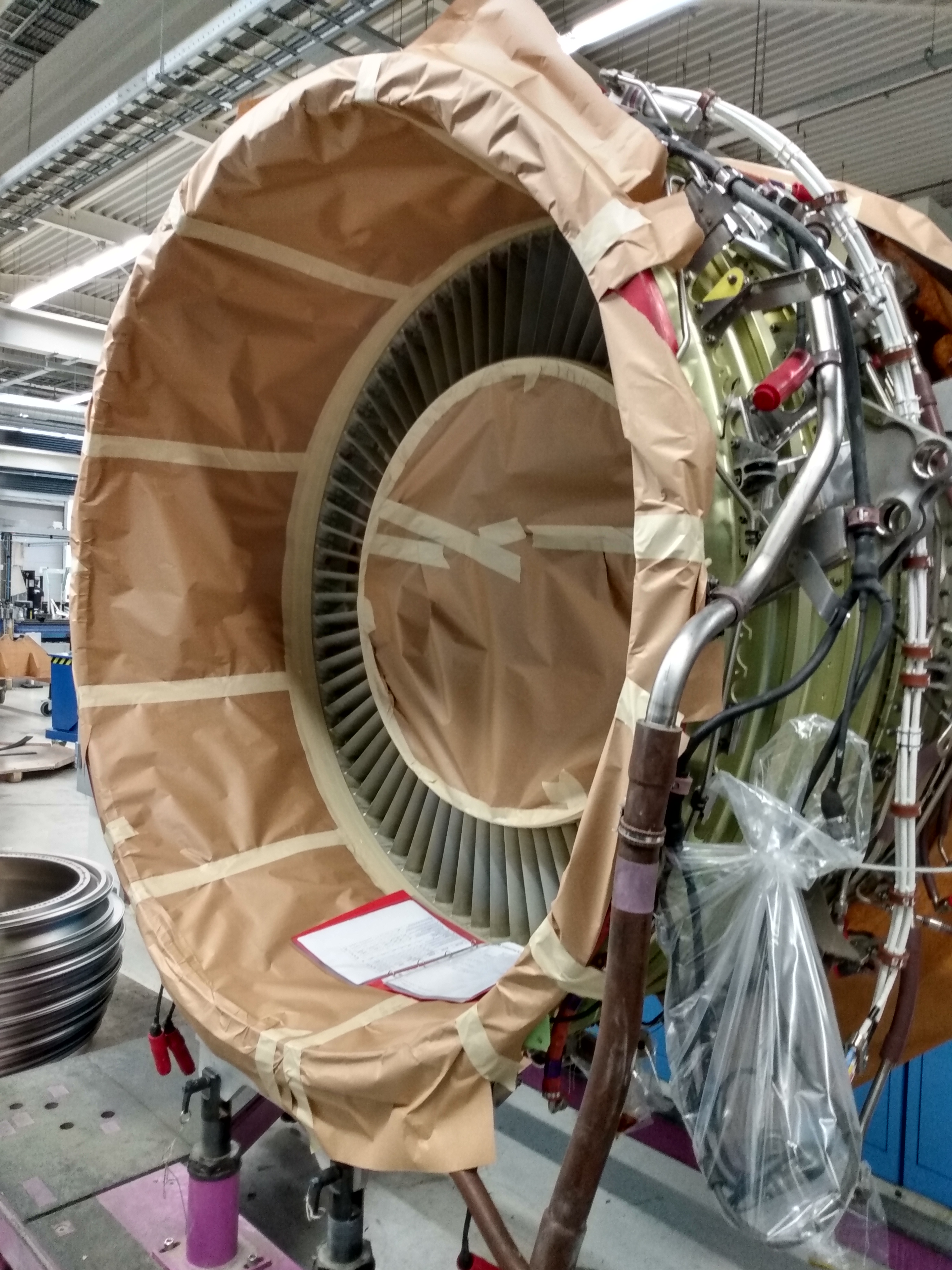
KLM Engineering & Maintenance is a big player in aircraft upkeep. They are located at Schiphol East. Engine Services is a part of the company that specializes in maintaining jet engines of all sorts. The engine most used (and most maintained) is a CFM56. When this engine is taken in, the Outlet Guide Vanes (OGV’s) need to be painted. When this is done, the fan casing itself should be kept blank.
The biggest selling point in maintenance is turnover time as airplanes only make money when they are being flown. Because of this, most processes are streamlined or automated for the least amount of waiting time.
Current situation
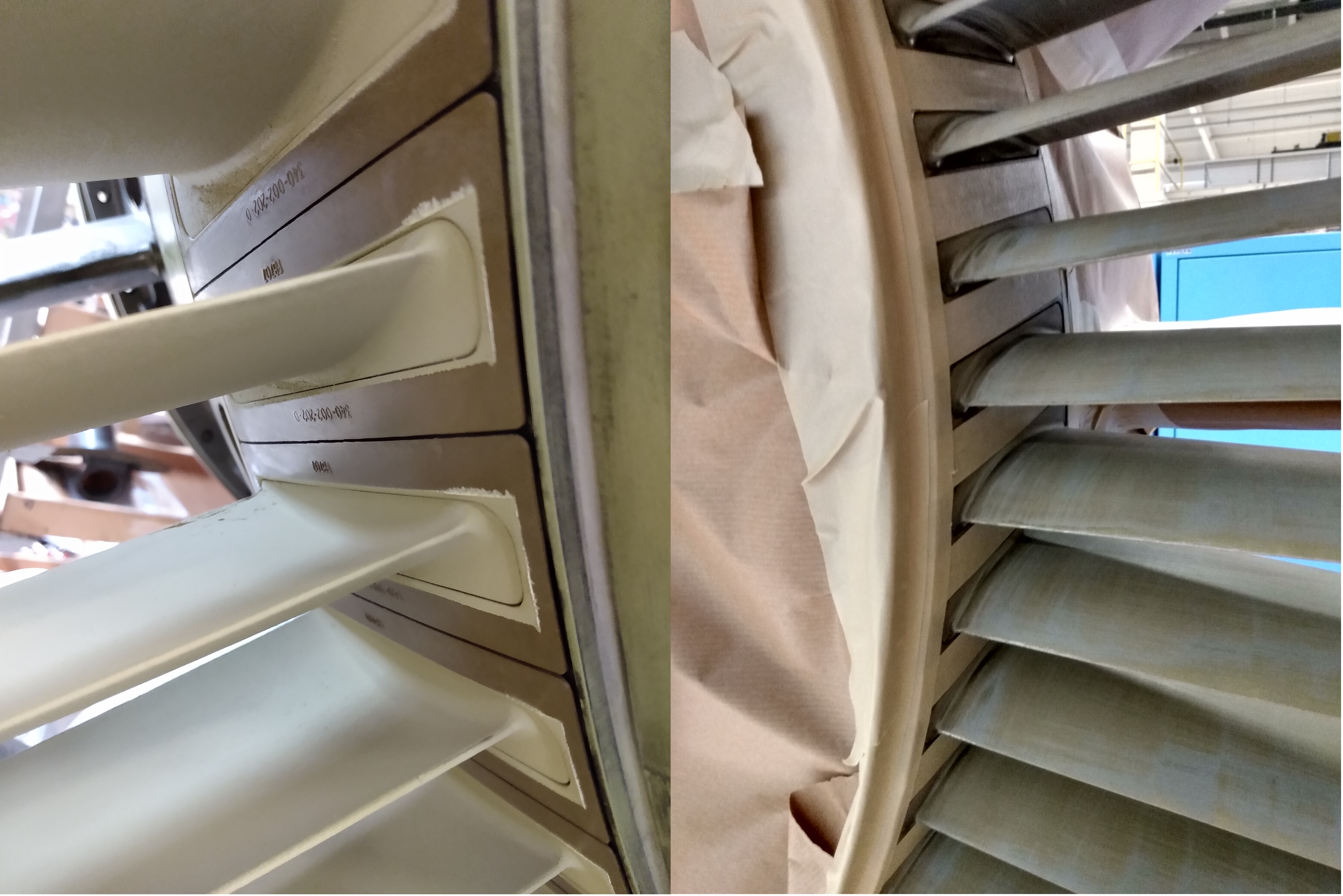
Right now, when a fan casing (the front part of a jet engine) needs to be painted, a painter applies masking tape between all OGV’s by hand. This is a tedious job and a full fan casing can take up to three hours to mask.
The goal
To make the job easier for the painters, a fully automated solution for masking is wanted. The robot needs to pick up tape and cut a long enough piece off. After that, it should put the masking tape between the OGV’s. In total this should happen 76 times per fan casing.
Challenges
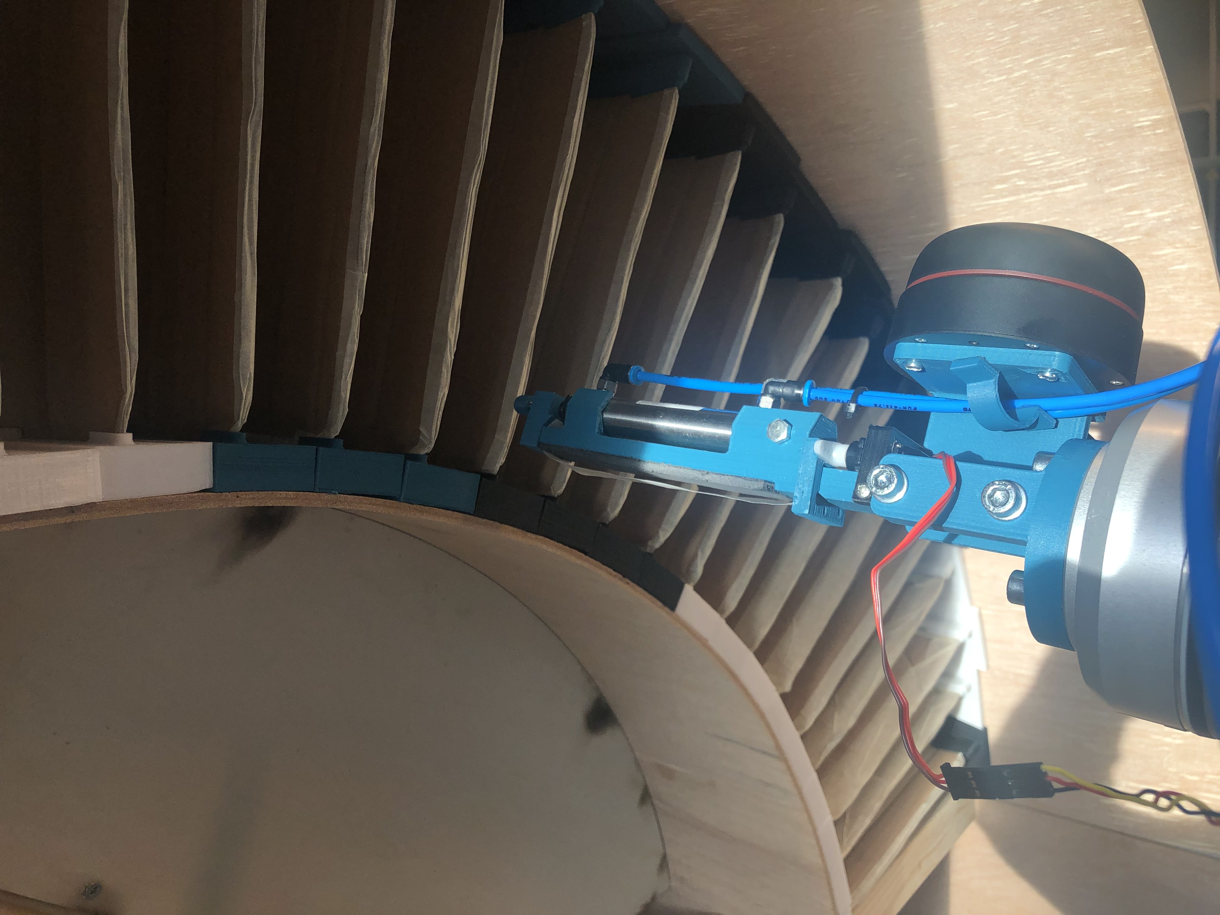
The space in between two vanes is 30 mm. This makes it very hard to perform all needed actions on the end of arm tool of the robot. Very accurate positioning is also key, as damaging the OGV’s or the fan casing is very expensive.
Our solution
The final solution makes use of a tape station, holding the tape and keeping it under tension. The end of arm tool holds the tape in place on both ends and cuts it off the roll. For the positioning, an RPLidar A2 is used. The program is divided in the following parts:
- First the lidar checks if the end of arm tool is in the fan casing. If it isn’t, it will move forward until it is.
- Next it moves to the tape station and clamps a piece of tape with a pneumatic cylinder. It then moves forward until the tape is fully under the end of arm tool and cuts the tape off using a servo with a knife attached to it.
- The robot will now move back into the fan casing, approximately where the vanes are located. The lidar will now scan to find the vanes and give an offset for the robot to move to.
- Lastly the robot will move the end of arm tool in between the vanes and it will apply the tape.
Major decisions
For the first iterations of the end of arm tool, the goal was to not use a tape station. It wasn’t possible to get this design as narrow as needed, so a tape station was made. For the positioning a lot of sensors have been tested, but a lidar turned out to be the most versatile and accurate.
Conclusion
Getting the robot as well as the lidar accurate enough to get into a 30 mm pathway with a 20 mm wide end of arm tool is certainly possible. To make the scanning quicker, a different lidar could be used.