Students: Christian Floris, Sammes de Haan, Melissa Damstra (2019).
![]()

Introduction
NeoTec Engineering is located in Hazerswoude-dorp and has employees with more than 15 years of experience. The company offers Consultancy, Engineering, Manufacturing and Assembling. It is a versatile partner and has a passion for the engineering field.
Assignment
NeoTec receives wafers from different companies in a number of branches, which have a top layer that needs to be tested on the adhesive anchorage. To test the wafers a grid needs to be cut into the top layer, a tape test must be executed and afterwards, the adhesive percentage must be defined. Each process is done by hand which makes the outcome unreliable. The cutting of the grid used inconsistent power and angles. Therefore, in 2017 a cutting tool was made to solve this problem.
Also, the adhesion check is done by eye, which means the results are incompatible with each other. These differences occur not only per person but also per sample. This results in an inaccurate testing percentage of how well the top layer is attached to the wafer. The process needs to be as consistent as possible. If this process also could be automated the results of the tape test will be more reliable.
Therefore, during the project, NeoTec would prefer a compact system that is able to place adhesive tape on a test wafer and removes this tape to test the adhesion of the top layer. This adhesion test should be checked and verified using a vision application. Also taken into consideration the possibility of immediately producing the system and the overall cost.
The system is meant to be a proof of concept approaching reality, with accompanying research into test consistency of man versus machine.
The solution
TARTAS is an abbreviation of the essence of the project: Tape Applier, Removal Tester and Analysis System. The project was executed within a time frame of 5 weeks. During the project, several design decisions were made which consist of multiple parts, like a Manipulator, Tape tester (which consist of an Input and Output mechanism), Wafer holder and a Vision system.
Manipulator
The manipulator consists of a framework and actuators. It is the main construction of the full system. The input mechanism is attached to the manipulator. Therefore, the manipulator must provide movement in the x and z-direction. This makes sure the input mechanism can apply tape to the test wafer.
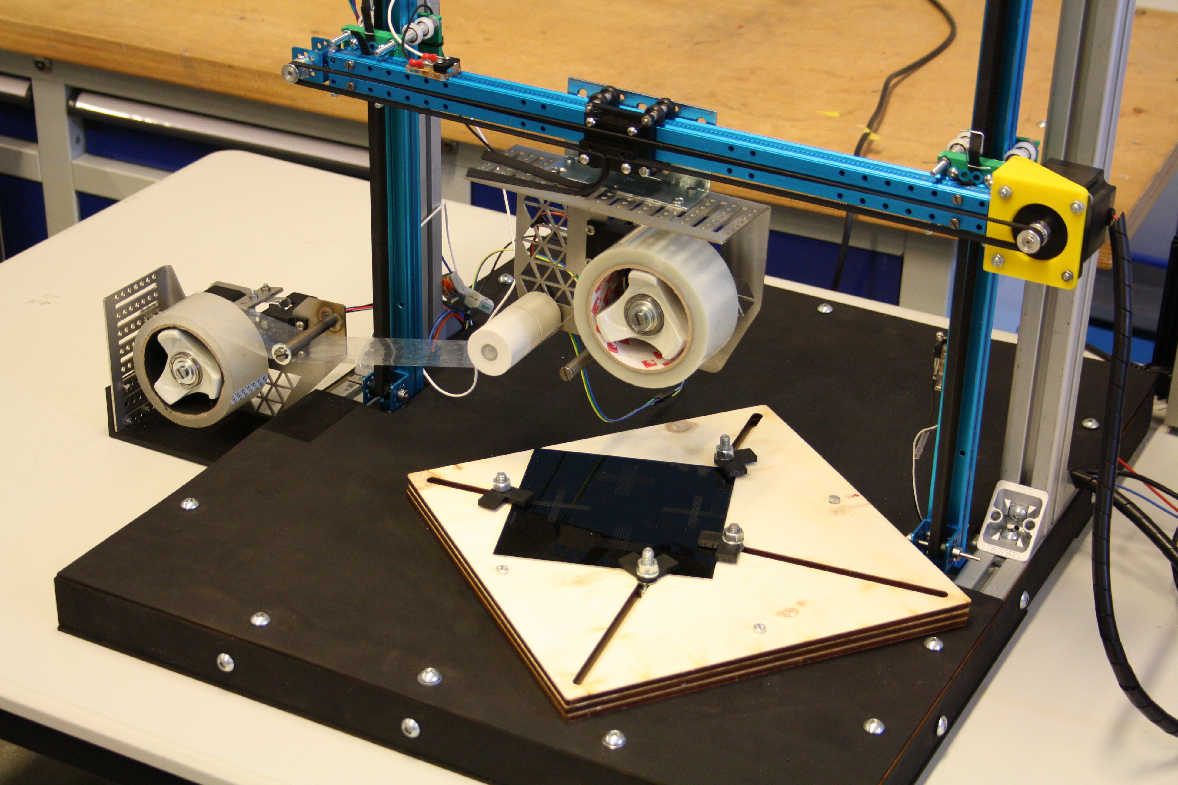
Figure 1: Framework of the manipulator with the input mechanism hanging on the beam, the output mechanism on the left attached to the frame and the wafer holder on the ground plate.
Tape Tester
The main decisions were made over the design of the tape tester. The first option was making one compact unit with all functions combined and the second option was spreading the functions throughout the system of the manipulator. Despite the engineering qualities of using one unit, due to build time the simplest design was chosen with the most passive components.
The tape tester is now divided into two different units called the “Input mechanism” and the “Output mechanism”. The Input unit moves due to the manipulator and the Output unit is attached to the frame of the manipulator, so it has a fixed position.
Input mechanism
The input mechanism is a tape applying tool. The mechanism moves downwards to the wafer due to the movements of the manipulator. The tape is pressed on the wafer while the roll of tape provides enough material.
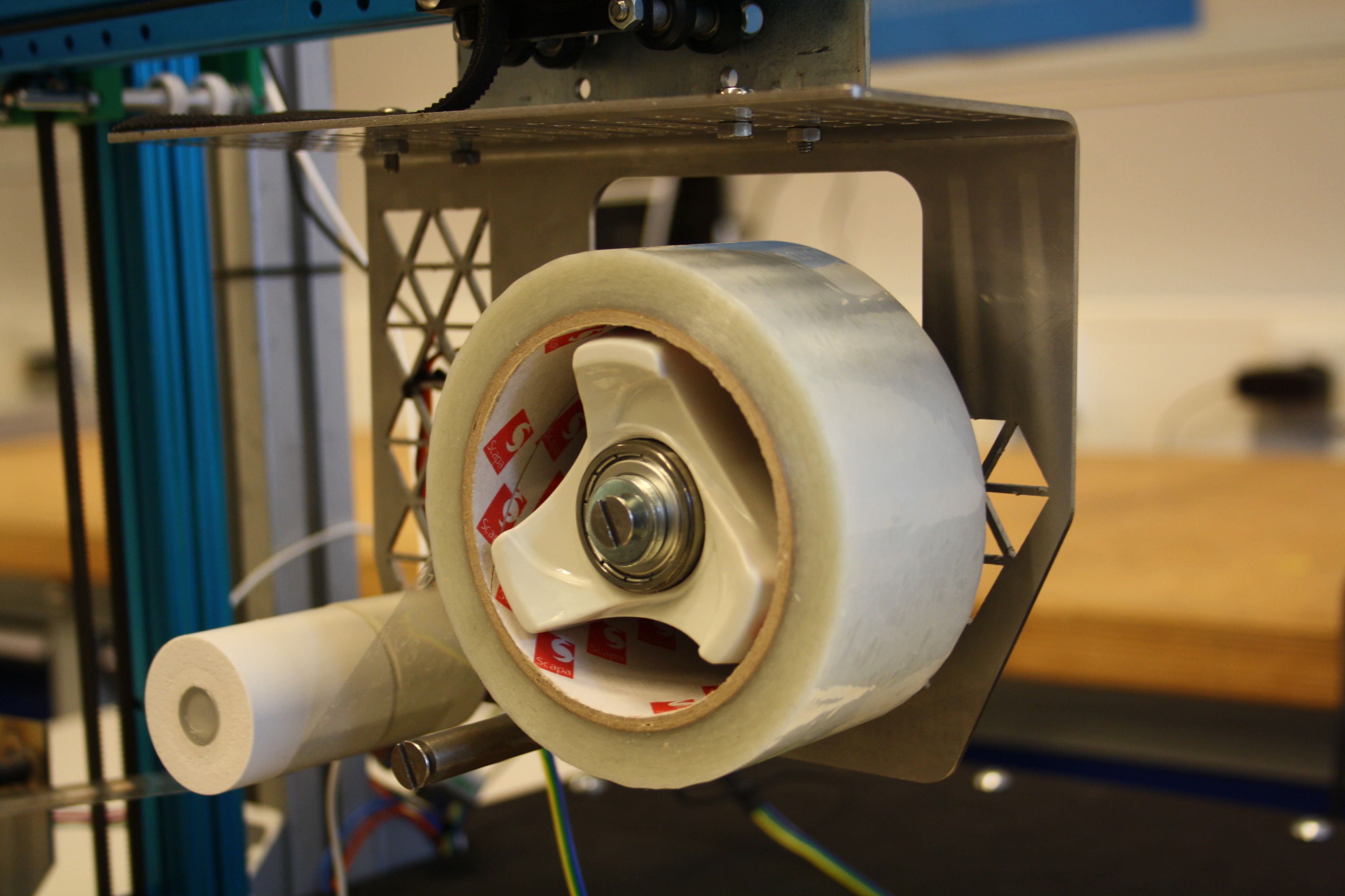
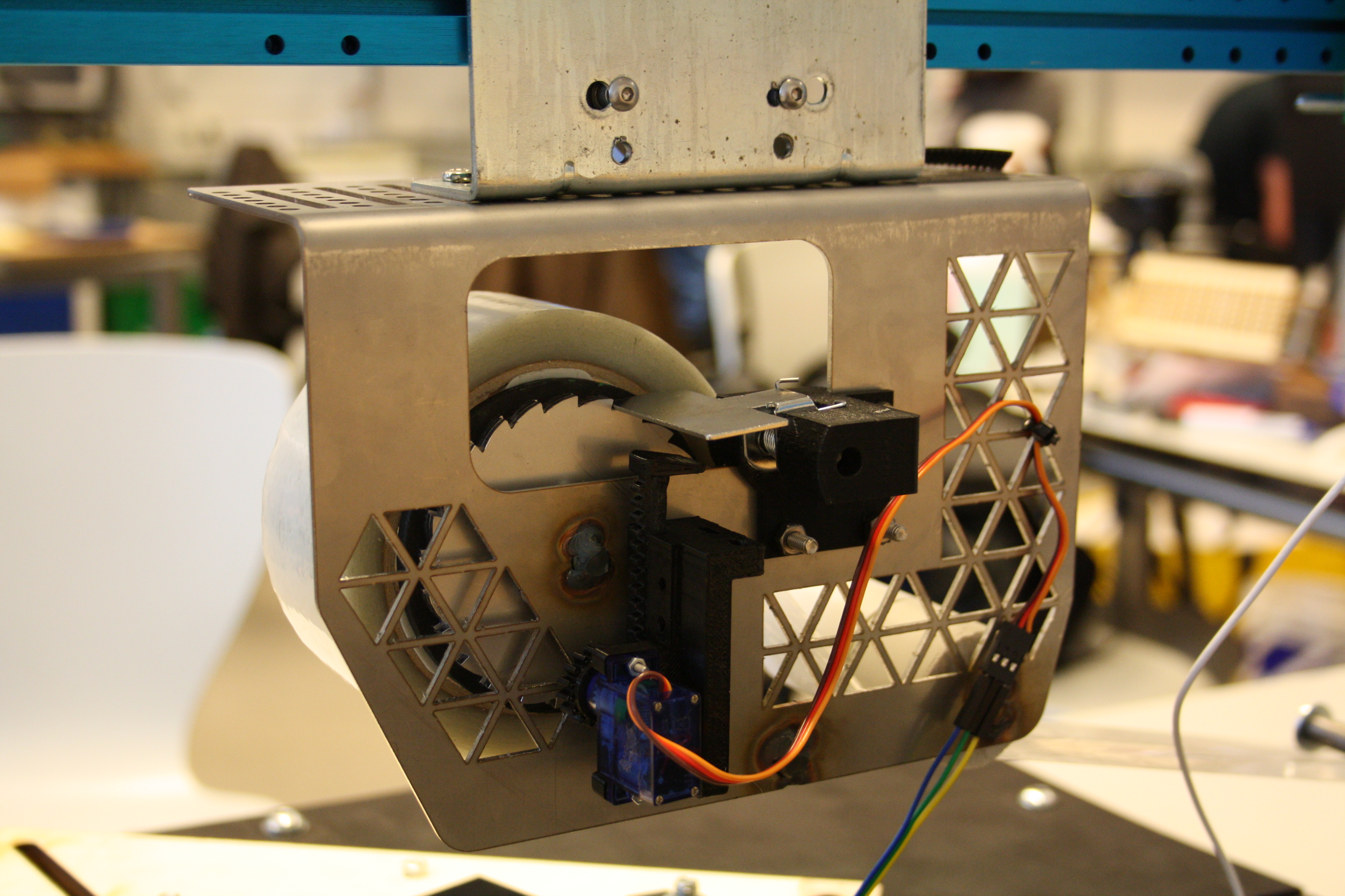
Figure 2: Input mechanism of the tape dispenser. On the left side the front of the mechanism and on the right the back of the mechanism.
Output mechanism
When the input mechanism has peeled off the tape on the wafer. The used tape must be collected, which is done by the output mechanism. The output tape roll will collect the used tape on the roll.
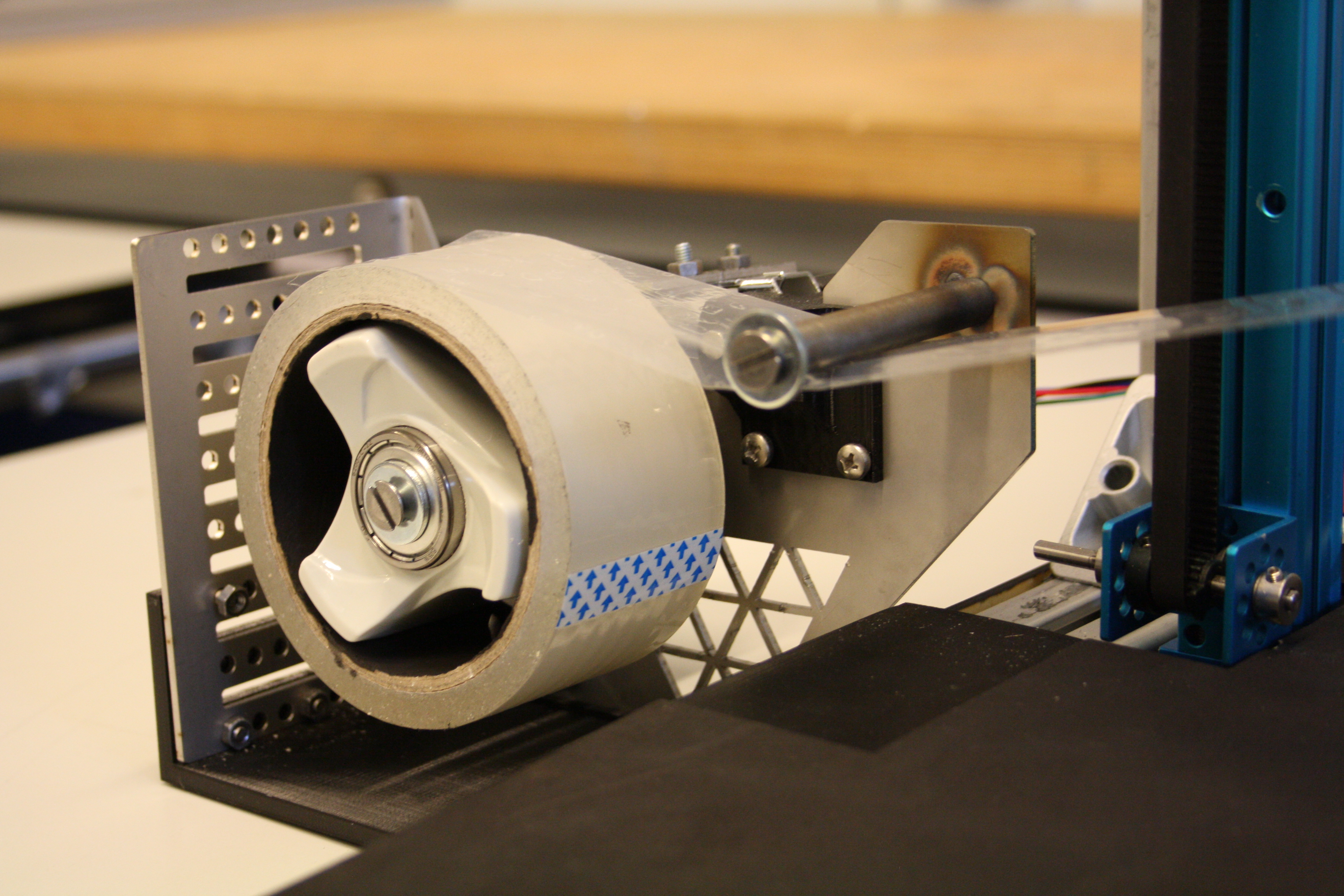
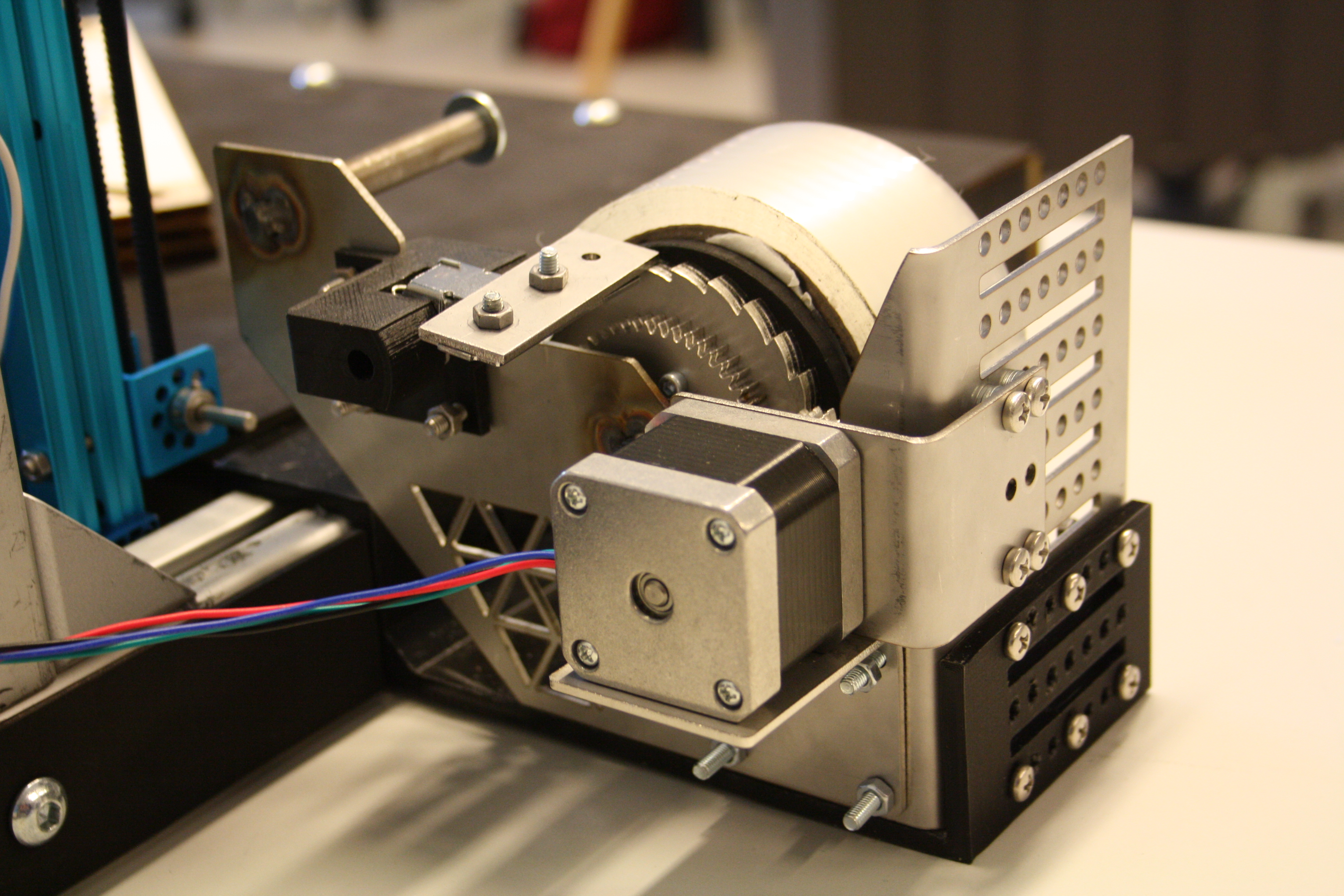
Figure 3: Output mechanism of the tape dispenser. On the left side the front of the mechanism and on the right the back of the mechanism.
Wafer holder
To place the wafer on a fixed position a wafer holder has been made. It is assembled on the ground plate so it can’t move. Due to the design of the holder, it is adjustable to wafers of different sizes. The corners can move to the wafer and be fastened, so the holder keeps the wafer in place by its corners.
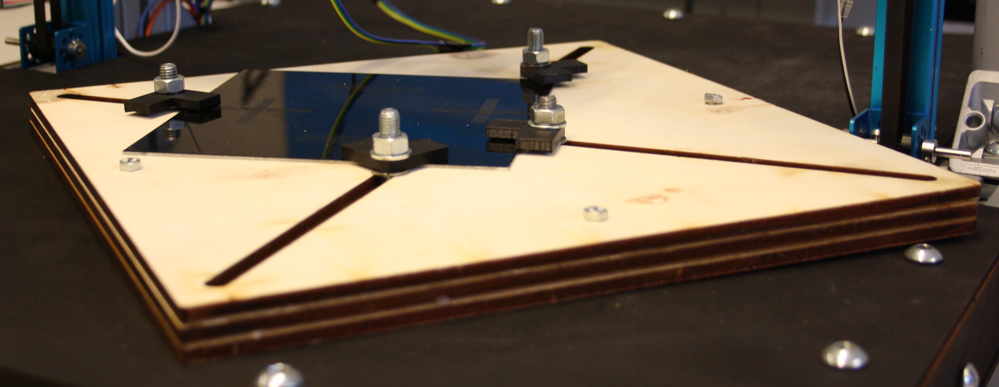
Figure 4: Wafer holder with attachment clips.
Vision System
For the setup of the vision system, a dome has been made. Within the dome, multiple components are added like a vision camera and lighting. The dome can be placed on the wafer and it makes sure no extra light can influence the quality check. Before the tape test is being executed the vision system takes a photo of the wafer. After the tape test, the vision system takes another photo of the wafer and compares the two.