[This assignment is part of Siemens’ greater project to automate twistlock handling. Due to the COVID-19 related lockdown this project assignment and the solution have been adapted to working from home, without a physical robot]
![]()
INTRODUCTION
In the handling of containers and transfer from ship to shore and vice-versa, the twistlocks that fasten containers together and secure the stacks, need to be removed from and placed in the corner castings (from now on referred to as CC’s) of the shipping containers.
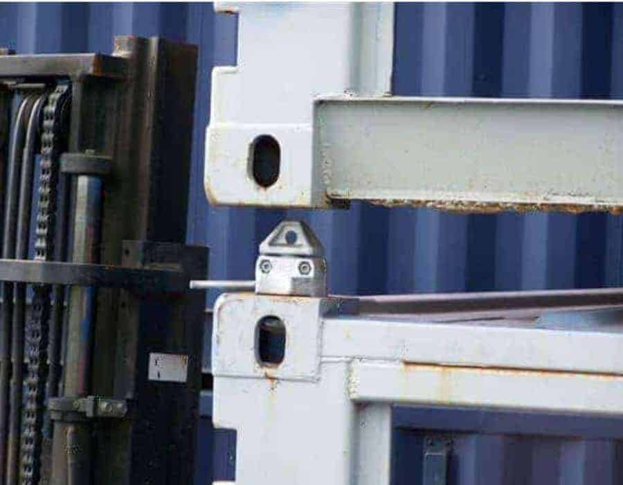
Figure 1 Twistlock used to fasten containers together.
(https://adaptainer.co.uk/wp-content/upload/2019/04/Shipping-container-twistlock-2.jpg)
This handling is at the time of writing a manual process, and Siemens is working on several projects to automate this process and work towards fully unmanned port cranes.
For twistlock handling the shipping containers are hanging from a crane and lowered where normally two people (one on each side of the container) remove or place two locks on the bottom corners of the container, so it can be placed and locked on board or on land.
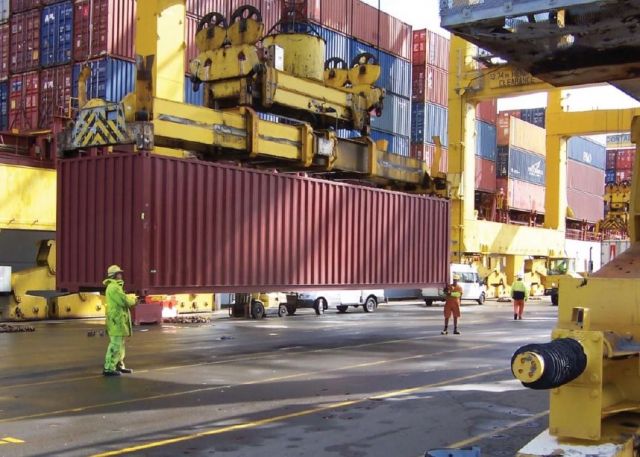
Figure 2 Manual twistlock removal/insertion by stevedores (https://www.portstrategy.com/__data/assets/image/0021/1206552/varieties/carousel2.jpg)
THE PROBLEM
The automation process of twistlock handling on port cranes is a complex one. While containers and their corner castings are fairly standardized, there are lots of different twistlock types that look and operate differently. Apart from that, because the container hangs from tethers, it is not perfectly still, but swings a bit from side to side, both in transversal and longitudinal direction. This adds complexity to the automation of twistlock handling since the robot must take the sway in account as well.
The swing of a container is not always the same, and cannot be easily predicted. Because of this, live tracking is necessary, and should be done accurately and confidently.
THE SOLUTION
The envisioned solution to the problem of swinging containers is the tracking of these movements to have the robot move along and compensate ensuring that it doesn’t become an issue when aiming to place or remove a lock. This proof of concept was developed in simulations only, without the physical robot or real moving containers. However, with the use of a CC and a RGB – depth camera (Intel Realsense D435), it was possible to experiment with an imitated sway of a container.
Machine learning recognition
In order to have the robot follow the movements of CC’s and not other objects, the CC should be recognized as such. Because the CC will be followed outside on the docks the recognition has to be very robust and work in various weather conditions. The best and most reliable way to do that is by applying machine learning.
Luckily, corner castings being standardized, have a well recognizable geometric profile; a square like box with an oval hole. With a self-made dataset of pictures (figure 3) in which both the CC and the hole were annotated, different YoloV5 models were trained. This was done via Google Colab on available GPU’s with different amounts of epochs to produce weight files (.pt) that can be used for visual detection in python scripts. This resulted in a confident detection of the CC and the hole (figure 4). To make the model more reliable in different conditions, more annotated and augmented pictures of this condition can be added to the dataset.
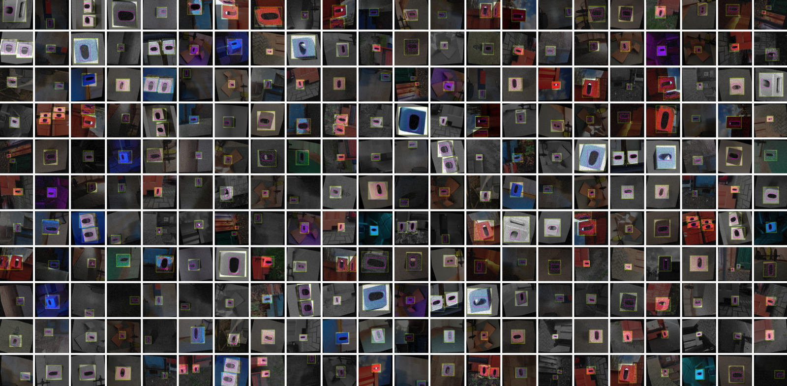
Figure 3 Roboflow dataset with annotations used for yolov5 training
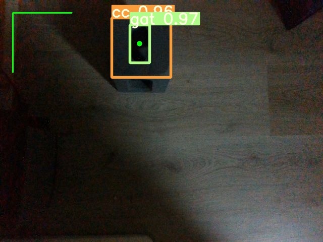
Figure 4 First test results from yolov5
Simulating different weather conditions
By applying various circumstances to the image we could determine the robustness of the machine learning weights. The detection with the Realsense camera performed great overall and managed to detect the CC and the hole when exposed to any daylight scenery, glare, bright spotlights, dirty/obstructed lens and in poor lighting conditions as shown in figure 5.
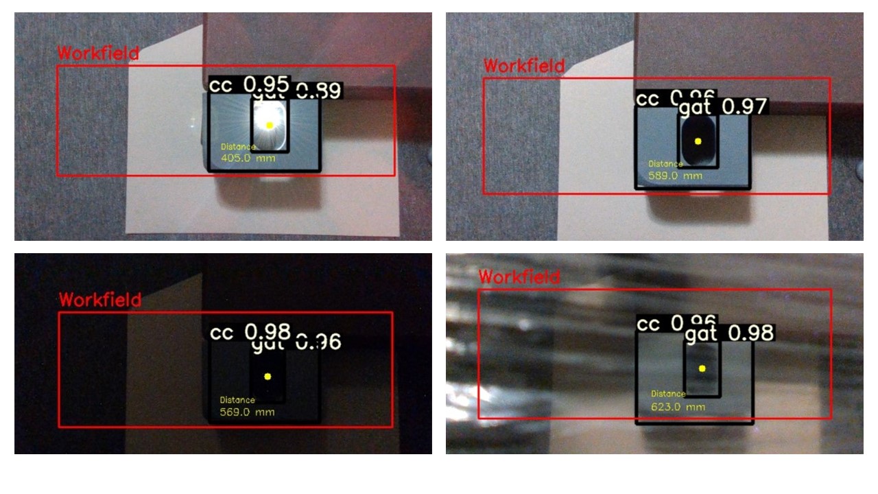 Figure 5 Cornercast detection in different weather conditions
Visual tracking
Apart from using detection for confirmation that there is in fact a CC in front of the camera, the bounding boxes from detection are also used to track the CC. The centre of the bounding box around the hole is the position that needs to be tracked. This is the basis of the tracking in the plane of the camera’s field of view. Because the container can also swing longitudinally, changes in distance between CC and camera need to be tracked as well. An Intel Realsense camera with depth detection was used to determine the distance and use this to move the robot accordingly to the longitudinal movements of the container. This distance is then shown in the video interface as shown in figure 6 . Using the difference of distances in X, Y coordinates from the centerpoint, shown as the green dot in the RGB image and the difference in depth (Z coordinate) between every following frame, the average velocity between two frames can be calculated. By multiplying the velocity with the delay of the executed script, the distance to compensate can be obtained.
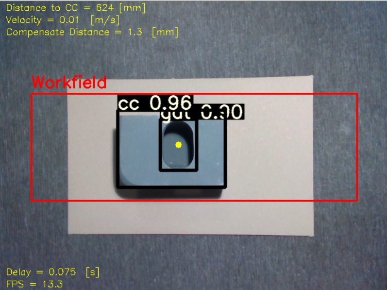
Figure 6 Final interface cornercast tracking
Digital twin & Camera-based robot control
For the proof of concept a digital testing environment was built in the RoboDK simulation software. The main advantage of this particular program is the possibility to control a real UR10 robot from a Windows computer, without the need for virtual machines.
To calibrate the robot simulator to the camera image a work field has been designed, which is visible in both aspects (as can be seen in figure 6 and 7). In this way points from the camera image can be matched to points in the simulator to control the robot. The standardized size of the CC, is used to scale the work field along with the distance to the CC.
In the simulation setup a UR10 robot was placed along with a “hanging” container, suspended in the air and movable. Some context was also added with more containers and a rail system that would be necessary should the robot handle different container sizes (20ft and 40ft).
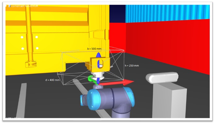
Figure 7 RoboDK simulation with workspace dimensions
The X-Y-Z coordinates tracked from the visual feed and the depth camera are sent to a script that links to RoboDK and commands the movement of the container. With a small delay, the robot also moves to this location. In reality, the container is already at the coordinate location and the robot would move toward this point. The delay added is equal to the processing time, so it represents the delay between real life input and the subsequent robot movement.
Optimalization
The delay of the python script is a very important aspect of this solution, because it greatly affects the precision of handling twistlocks. The speed can mostly be increased by optimizing the code and having processes run parallel to each other; so-called multi-threading. Cleaning up unnecessary pieces of code also helped achieve a steady 15 frames per second including all the processing of detection and tracking. This is the limit of our personal hardware. Greater speeds can be achieved using more advanced processing units.
IMPLEMENTATION
This solution is part of the greater project Siemens has at hand, and to implement this it’s important to keep in mind that the Program RoboDK can be used to control a real robot. With this program Siemens is able to map the average delay created when using machine vision to track a container. The information about this delay will help them in choosing the continuation of this project. They now know the distance and time the robot has to make up to the container.
The code should be changed to move only the robot with no “extra” delay, only the real processing time. The container can be removed from the move commands, and even from the digital environment.
A compliant tool for twistlock handling is still necessary and should be able to compensate for precision margins and tolerances in the follow-movement.
An in-depth evaluation of hardware should be done to achieve the best processing time possible and avoid delay in the robot movement.