Students: Mohamed Khedr, Nick Botermans (2022)
Introduction
SOWNet technologies is a Dutch company specializing in wireless sensor networks. The company was founded in 2006 as a spin-off of the research institute TNO, core area of Defense and Security. One of their remarkable products is the sowet-module which is like a universal communication module for different types of sensors.
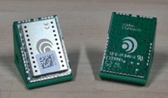
Figure 1: Universal communication modules
Current situation
Currently, SoWNet programmes the modules manually using a custom-made programming station. A person must manually input one module at a time on the programming probes so that the module can be programmed successfully.
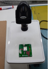
Figure 2: Current situation
The problem
Human programming the module’s manual is a very slow and tiring process because the modules must be always placed on the programming probes for successful programming. Therefore, it takes many days to finish a client’s order as the order may require thousands of modules.
The slow programming speeds required the company an automated way to program plates with modules.
The solution
Our solution includes using a lift system with two buffers (one for input plates and the other as an output). Using a linear movement mechanism by using stepper motors in combination with a linear axis, we can move the buffers, programming station, and the plates.
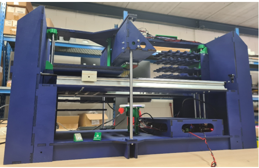
Figure 3: The machine
The module plates can be moved by two platforms that hold them through the whole process.
We use a webcam from a fixed place to read the numbers of the modules through data matrixes. The reading happens one row from a plate at a time.
The plates go next to the programming station, where the modules are programmed one at a time per row by multiplexing the signal. The programming probes move from the top to the bottom to reach the row of modules.
After the programming of each module is finished, a file is created with the identification numbers from each module with its corresponding programming status; either correctly programmed or incorrectly programmed.
Finally, the plates are moved to the output buffer as storage.
The user can control the system via an HMI, where the user can start or the process or home the stepper motors to their starting positions. The HMI will not allow the user to start the process unless the stepper motors are first homed.
The HMI also show a grid of 25 circles that corresponds to a module plate with its corresponding module numbers under each circle. A green circle means programming is successful and a red one means unsuccessful programming due to internal problems with the module itself or a bad connection between the probes and the pads. The grid is updated per module plate.
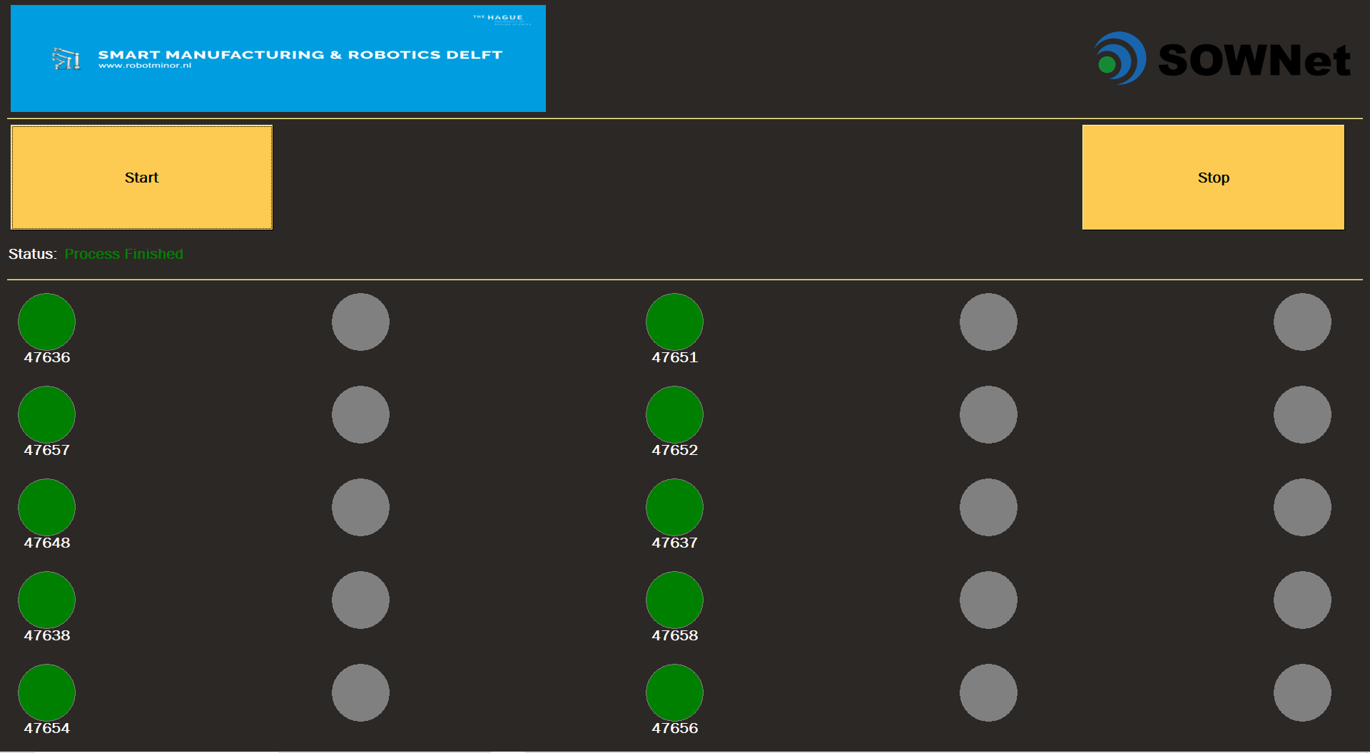
Figure 4: HMI
Major decisions
A major decision with this project is the mechanical design. At first our mechanical design consisted of a rotary table with placeholders for the module plates with a fixed place for the webcam and the programming station. This idea was dismissed as our client chose the lift system, because the rotary table idea took too much space and it looked clumsy.
Secondly, we switched from one type of motor driver to another (DVR8825 to TMC2208), because the first type used too much current and current fluctuations were too high. That led to the mechanism making too much noise and with the desired speeds made the motor drivers very hot in temperature. The current type of motor driver uses less current and it has a built-in noise canceling motor control.
Thirdly, we switched from using a demultiplexer to relays to multiplex the programming signal. That is because the RDS (Resistance drain to source) is too high and therefore making multiplexing not completely analog. This led to the multiplexed signal being lower than the module’s low threshold. We have decided to use relays for multiplexing the programming signal because then we know for sure that the multiplexed signal is transmitted analogously.
Lastly, the company decided to redesign its modules to have bigger programming pads in a more convenient place. This decision was concluded due to our research and explanation with our client that the margin on the module’s programming pads was too small making the associated programming probes extend outside the pads. This led to our system working as planned, but not consistently on the programming of the modules. By making the programming pads bigger and changing the pad positions, it is then easier and more reliable to program the modules with programming probes.
Conclusion
We delivered on the goal of building a system that can program modules automatically in patches, to give an overview of which modules were programmed, can be controlled, and have their status viewed via an HMI. The company will change the layout of some of the pads and their position so that our machine is more reliable.
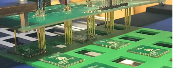
Figure 5: Connecting to the modules
Acknowledgments
We would like to thank Winelis Kavelaars, Kevin Oei and Rafaël Vuijk from SoWNet Technologies for their help.
Our gratitude extends also to Thijs Brilleman and Mathijs van der Vegt for their expertise and support during this project.